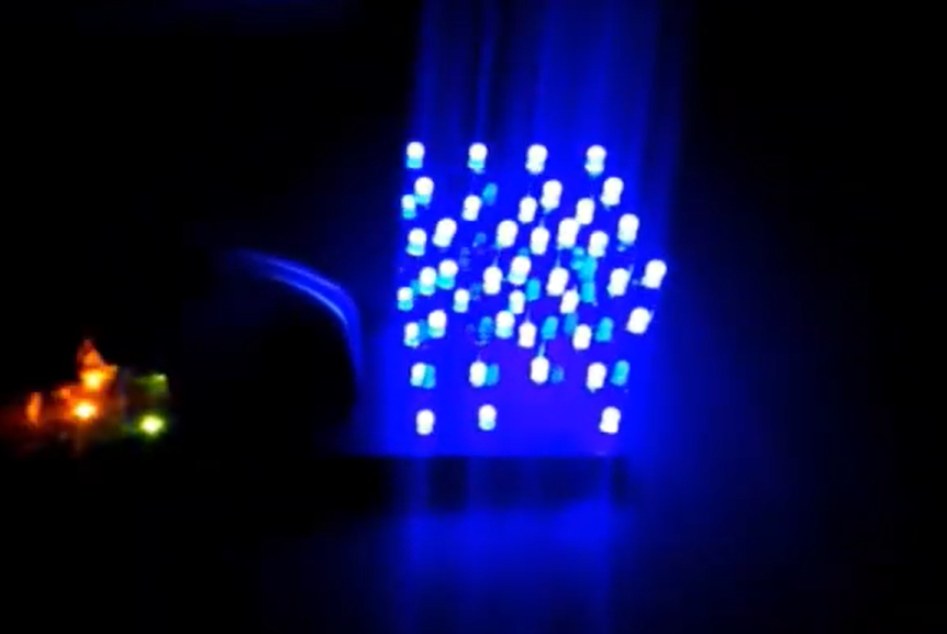
This project showcases the capabilities of an Arduino Uno in controlling 9 LEDs to create a dynamic and visually engaging random blinking display. By implementing various blinking patterns, the LEDs can be made to blink sequentially, simultaneously, or randomly, providing an interesting and educational project for enthusiasts of all levels.
Components Needed:
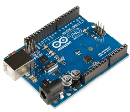
- Arduino Uno
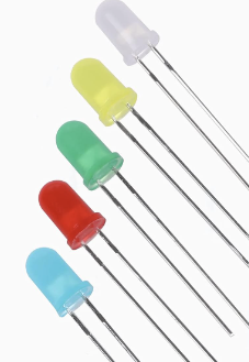
- 9 LEDs
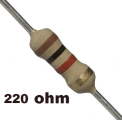
- 9 current-limiting resistors (220Ω to 330Ω recommended)
- Breadboard and jumper wires
Circuit Connections:
LEDs and Resistors:
- Connect the anode (longer leg) of each LED to one end of a current-limiting resistor.
- Connect the other end of the resistor to a digital pin on the Arduino Uno.
Breadboard Setup:
- Place the LEDs on the breadboard.
- Connect the cathode (shorter leg) of each LED to the ground rail of the breadboard.
Pin Assignments:
- LED 1: Connect anode (through resistor) to pin 2 on the Arduino Uno.
- LED 2: Connect anode (through resistor) to pin 3 on the Arduino Uno.
- LED 3: Connect anode (through resistor) to pin 4 on the Arduino Uno.
- LED 4: Connect anode (through resistor) to pin 5 on the Arduino Uno.
- LED 5: Connect anode (through resistor) to pin 6 on the Arduino Uno.
- LED 6: Connect anode (through resistor) to pin 7 on the Arduino Uno.
- LED 7: Connect anode (through resistor) to pin 8 on the Arduino Uno.
- LED 8: Connect anode (through resistor) to pin 9 on the Arduino Uno.
- LED 9: Connect anode (through resistor) to pin 10 on the Arduino Uno.
Ground Connections:
- Connect the ground rail of the breadboard to one of the GND pins on the Arduino Uno.
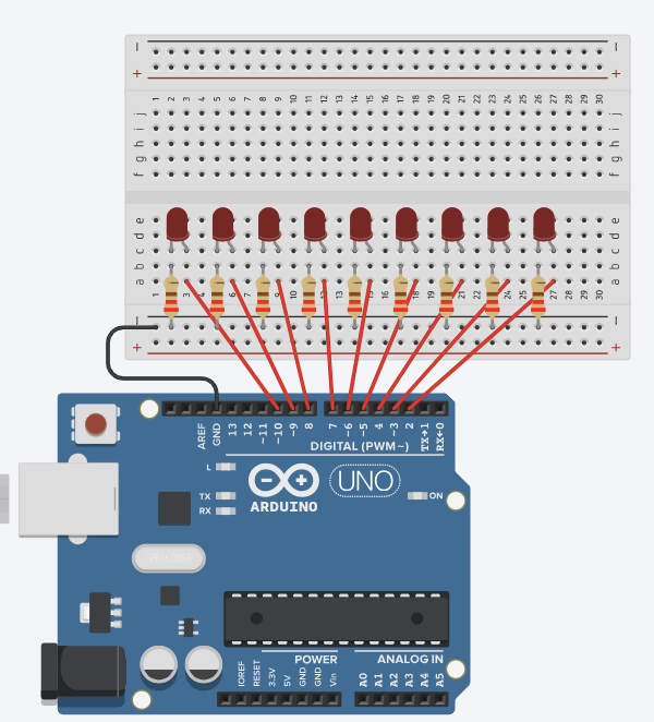
Circuit diagram is given below:
Code is given below:
const int ledPins[9] = {2, 3, 4, 5, 6, 7, 8, 9, 10};

void setup() {
  // Initialize all LED pins as outputs
  for (int i = 0; i < 9; i++) {
    pinMode(ledPins[i], OUTPUT);
    digitalWrite(ledPins[i], LOW); // Ensure all LEDs are off initially
  }
}

void pattern1() {
  // Sequentially turn each LED on and off
  for (int i = 0; i < 9; i++) {
    digitalWrite(ledPins[i], HIGH);
    delay(50);
    digitalWrite(ledPins[i], LOW);
  }
}

void pattern2() {
  // Randomly select an LED, turn it on briefly, then off
  for (int i = 0; i < 10; i++) {
    int randomIndex = random(0, 9);
    digitalWrite(ledPins[randomIndex], HIGH);
    delay(100);
    digitalWrite(ledPins[randomIndex], LOW);
  }
}

void pattern3() {
  // Turn all LEDs on simultaneously, wait, then turn them off
  for (int i = 0; i < 9; i++) {
    digitalWrite(ledPins[i], HIGH);
  }
  delay(200);
  for (int i = 0; i < 9; i++) {
    digitalWrite(ledPins[i], LOW);
  }
  delay(200);
}

void pattern4() {
  // Blink all LEDs on and off together
  for (int j = 0; j < 5; j++) {
    for (int i = 0; i < 9; i++) {
      digitalWrite(ledPins[i], HIGH);
    }
    delay(100);
    for (int i = 0; i < 9; i++) {
      digitalWrite(ledPins[i], LOW);
    }
    delay(100);
  }
}

void loop() {
  // Select a random pattern and execute it
  int pattern = random(1, 5); // Randomly choose a pattern number between 1 and 4

  switch (pattern) {
    case 1:
      pattern1();
      break;
    case 2:
      pattern2();
      break;
    case 3:
      pattern3();
      break;
    case 4:
      pattern4();
      break;
  }

  delay(500); // Delay between patterns
}
Features:
- Sequential Blinking: LEDs light up one after the other, creating a wave-like effect.
- Random Blinking: LEDs blink randomly, giving an unpredictable and lively display.
- Simultaneous Blinking: All LEDs turn on and off together, creating a uniform flash.
- Grouped Blinking: LEDs blink on and off in quick succession, creating a strobe-like effect.
Application:
Educational Tool:
- Learning Microcontroller Programming: The project introduces beginners to the basics of programming microcontrollers, including concepts such as pin configuration, digital output control, looping, and randomization.
- Understanding Electronics: By building the circuit and implementing the code, enthusiasts gain hands-on experience with fundamental electronic components and principles, such as LEDs, resistors, and breadboard wiring.
Visual Displays:
- Art Installations: The random and dynamic blinking patterns can be used to create visually appealing art installations or interactive displays in galleries and public spaces.
- Decorative Lighting: This project can be adapted for decorative lighting in homes, events, or festivals, providing a unique and customizable lighting effect.
Interactive Exhibits:
- Science Museums: The project can be integrated into exhibits to demonstrate principles of electronics and programming in an engaging and interactive manner.
- Tech Workshops: Useful for hands-on workshops where participants can learn about Arduino and electronics through building and programming their own LED displays.
Prototyping and Testing:
- Circuit Design: Engineers and hobbyists can use this project to prototype and test circuits involving multiple LEDs and understand the effects of different blinking patterns.
- Debugging Tools: The LED blinking patterns can serve as visual indicators in larger projects, helping to debug and visualize the state of different components or systems.
Entertainment and Games:
- Game Development: Developers can use the random LED patterns to create light-based games or puzzles, where players interact with the LEDs in various ways.
- Interactive Toys: This project can be incorporated into toys to add an element of interactivity and visual appeal, making them more engaging for users.