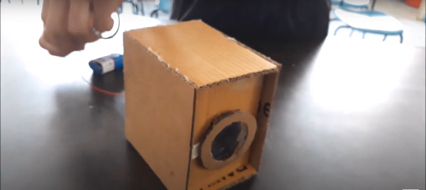
Automatic Garbage Collector project is about making a quiet robot that collects garbage. It uses a special card near the door to know when to come inside. When it arrives, it makes a buzzer sound and flashes a light. The robot follows a dark path using sensors, going from door to door to pick up garbage. It’s all controlled by an Arduino and a motor driver to move smoothly and quietly around homes, Automatic Garbage Collector Project for students
Components Required:
- Arduino Board: 1
- RFID Module (e.g., MFRC522): 1
- RFID Card: 1
- Motor Driver Module (e.g., L298N): 1
- DC Motors: 2
- IR Sensors: 2
- Buzzer: 1
- LED: 1
- I2C LCD Module (e.g., 16×2): 1
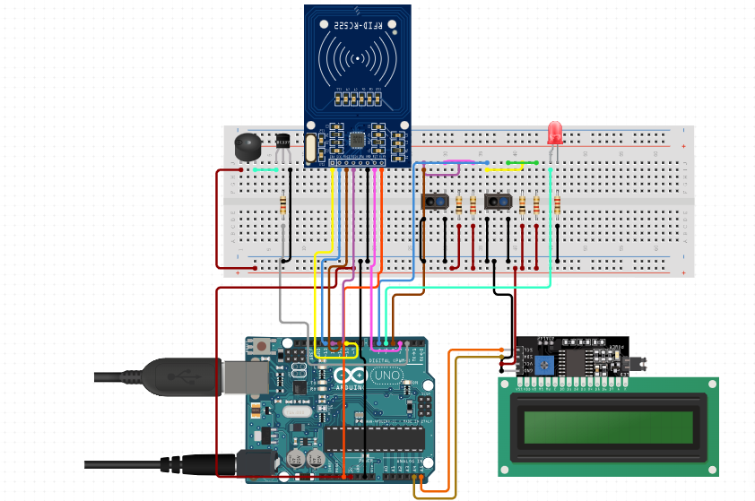
Connections:
- RFID Module (MFRC522):
- SDA: Connect to digital pin 10 (SS_PIN)
- SCK: Connect to digital pin 13 (SPI SCK)
- MOSI: Connect to digital pin 11 (SPI MOSI)
- MISO: Connect to digital pin 12 (SPI MISO)
- RST: Connect to digital pin 9 (RST_PIN)
- 3.3V: Connect to 3.3V pin on Arduino
- GND: Connect to GND pin on Arduino
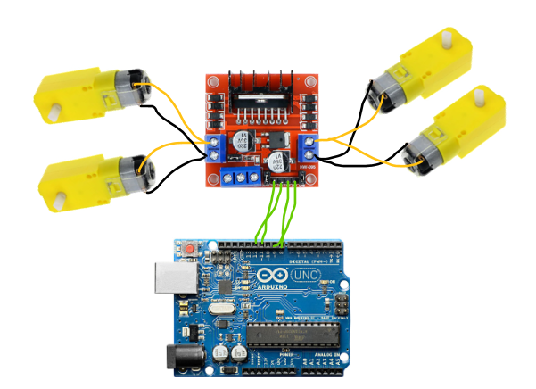
- Motor Driver Module (e.g., L298N):
- Motor 1 Control:
- Input 1 (IN1): Connect to digital pin 2 (motor1A)
- Input 2 (IN2): Connect to digital pin 3 (motor1B)
- Motor 2 Control:
- Input 3 (IN3): Connect to digital pin 4 (motor2A)
- Input 4 (IN4): Connect to digital pin 5 (motor2B)
- VCC: Connect to external power supply positive (e.g., 12V)
- GND: Connect to external power supply negative and Arduino GND
- Motor 1 Control:
- IR Sensors:
- Left IR Sensor: Connect analog output to analog pin A0 (leftIRSens)
- Right IR Sensor: Connect analog output to analog pin A1 (rightIRSens)
- VCC: Connect to 5V pin on Arduino
- GND: Connect to GND pin on Arduino
- Buzzer and LED:
- Buzzer: Connect positive pin to digital pin 6 (buzzerPin), negative to GND
- LED: Connect positive pin to digital pin 7 (ledPin), negative to GND
- I2C Communication:
- SDA: Connect to analog pin A4 (SDA)
- SCL: Connect to analog pin A5 (SCL)
- VCC: Connect to 5V pin on Arduino
- GND: Connect to GND pin on Arduino
- Mini Breadboard
#include <Wire.h>
#include <LiquidCrystal_I2C.h>
#include <SPI.h>
#include <MFRC522.h>

#define SS_PIN 3   // Slave Select Pin for RFID module
#define RST_PIN 10   // Reset Pin for RFID module

MFRC522 mfrc522(SS_PIN, RST_PIN);  // Create instance of MFRC522

// Define pins for motor driver
const int motor1A = 11;  // Motor 1 control pin A
const int motor1B = 12;  // Motor 1 control pin B
const int motor2A = 8;  // Motor 2 control pin A
const int motor2B = 9;  // Motor 2 control pin B
// Define pins for IR sensors
const int leftIRSens = 4;   // Analog pin for left IR sensor
const int rightIRSens = 6;  // Analog pin for right IR sensor

// Define pins for buzzer and LED
const int buzzerPin = 2;
const int ledPin = 5;

// I2C LCD
LiquidCrystal_I2C lcd(0x27, 16, 2); // Address 0x27, 16 columns, 2 rows

void setup() {
  Serial.begin(9600);  // Initialize serial communication
  Wire.begin();        // Init I2C bus
  mfrc522.PCD_Init();  // Init RFID module
  lcd.begin();          // Initialize the LCD
  lcd.backlight();     // Turn on the backlight

  // Set motor control pins as output
  pinMode(motor1A, OUTPUT);
  pinMode(motor1B, OUTPUT);
  pinMode(motor2A, OUTPUT);
  pinMode(motor2B, OUTPUT);

  // Set IR sensor pins as input
  pinMode(leftIRSens, INPUT);
  pinMode(rightIRSens, INPUT);

  // Set buzzer and LED pins as output
  pinMode(buzzerPin, OUTPUT);
  pinMode(ledPin, OUTPUT);

  // Stop motors initially
  stopMotors();
}

void loop() {
  // Scan for RFID cards
  if (mfrc522.PICC_IsNewCardPresent() && mfrc522.PICC_ReadCardSerial()) {
    // Card detected, activate buzzer and LED
    digitalWrite(buzzerPin, HIGH);
    digitalWrite(ledPin, HIGH);
    lcd.clear();
    lcd.setCursor(0, 0);
    lcd.print("DUMP YOUR");
    lcd.setCursor(0, 1);
    lcd.print("GARBAGE");
    delay(1000);  // Keep buzzer and LED on for 1 second
    digitalWrite(buzzerPin, LOW);
    digitalWrite(ledPin, LOW);

    // Move forward to collect garbage
    moveForward();
    delay(3000);  // Adjust as needed for robot movement time

    // Check IR sensors for obstacles
    if (analogRead(leftIRSens) > 500 || analogRead(rightIRSens) > 500) {
      // Obstacle detected, stop and turn
      stopMotors();
      delay(1000);
      if (analogRead(leftIRSens) > analogRead(rightIRSens)) {
        turnLeft();
      } else {
        turnRight();
      }
      delay(1000);
    } else {
      // No obstacle, continue moving forward
      moveForward();
    }
  } else {
    // No card detected, stop motors
    stopMotors();
    lcd.clear(); // Clear LCD display
  }

  delay(100);  // Adjust delay for loop stability
}

// Function to move robot forward
void moveForward() {
  digitalWrite(motor1A, HIGH);
  digitalWrite(motor1B, LOW);
  digitalWrite(motor2A, HIGH);
  digitalWrite(motor2B, LOW);
}

// Function to turn robot right
void turnRight() {
  digitalWrite(motor1A, HIGH);
  digitalWrite(motor1B, LOW);
  digitalWrite(motor2A, LOW);
  digitalWrite(motor2B, HIGH);
}

// Function to turn robot left
void turnLeft() {
  digitalWrite(motor1A, LOW);
  digitalWrite(motor1B, HIGH);
  digitalWrite(motor2A, HIGH);
  digitalWrite(motor2B, LOW);
}

// Function to stop robot
void stopMotors() {
  digitalWrite(motor1A, LOW);
  digitalWrite(motor1B, LOW);
  digitalWrite(motor2A, LOW);
  digitalWrite(motor2B, LOW);
}