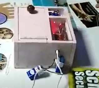
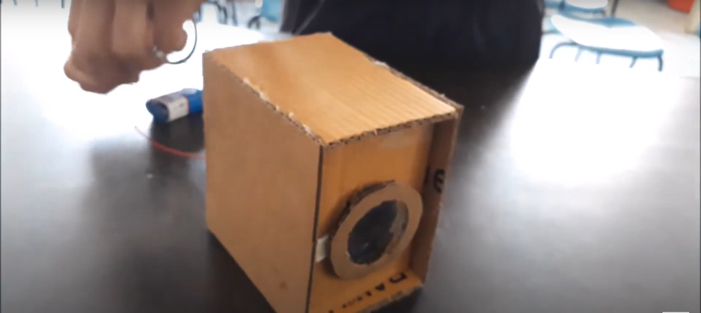
In this project, we created a special pair of smart glasses using an Arduino board, an ultrasonic sensor, and a buzzer. These glasses help visually impaired people detect obstacles in their path.
Component Required:
- Arduino Uno & Cable x1
- Ultrasonic Sensor x1
- Buzzer x1
- Jumper wires (male to male & male to female)
Component Overview:
- Arduino Board:
The Arduino is like the brain of our project. It controls everything and makes sure all the parts work together.
- Ultrasonic Sensor:
We attached an ultrasonic sensor to the glasses. This sensor sends out sound waves (like a bat) and measures how long it takes for them to bounce back. This helps it figure out how far away objects are.
- Buzzer:
We also added a buzzer to the glasses. When the ultrasonic sensor detects something close, the buzzer makes a sound to warn the person wearing the glasses.
Putting It All Together
- Building the Circuit:
- We connected the ultrasonic sensor and the buzzer to the Arduino board with wires. We also wrote some code to tell the Arduino what to do.
- Attaching to the Glasses:
- We carefully attached the ultrasonic sensor to the front of the glasses so it could “see” what’s ahead. We put the Arduino board and buzzer on the side of the glasses.
Futuristic approach for helping people:
When a person wears these smart glasses, the ultrasonic sensor constantly checks for obstacles in front of them. If something is too close, the buzzer will beep to let them know. This way, visually impaired people can walk around more safely without bumping into things.
Why It’s Importance of this project:
This project helps blind people by giving them a simple and effective tool to navigate their surroundings. It shows how technology can be used to make life easier and safer for everyone.
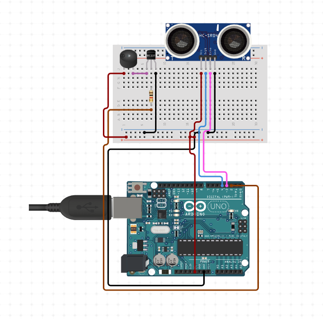
Pin Connections:
1. HC-SR04 Ultrasonic Sensor:
- VCC to 5V on Arduino
- GND to GND on Arduino
- Trig to Pin 9 on Arduino
- Echo to Pin 10 on Arduino
2. Push Button:
- One leg of the button to 5V on Arduino
- Other leg of the button to a 220-ohm resistor which then goes to GND on the breadboard
- Same leg of the button that is connected to the resistor to Pin 8 on Arduino
3. Buzzer with NPN Transistor:
- Collector of NPN transistor to negative terminal of the buzzer
- Positive terminal of the buzzer to 5V on Arduino
- Emitter of NPN transistor to GND on Arduino
- Base of NPN transistor to one end of a 10k ohm resistor
- Other end of the 10k ohm resistor to Pin 11 on Arduino
SOURCE CODE:

#include <Wire.h>
#include <LiquidCrystal_I2C.h>

// Set the LCD address to 0x27 for a 16 chars and 2 line display
LiquidCrystal_I2C lcd(0x27, 16, 2);

// Define pins for the ultrasonic sensor
const int trigPin = 9;
const int echoPin = 10;

// Define pin for the button
const int buttonPin = 8;

// Variable to store the duration and distance
long duration;
int distance;

void setup() {
  // Initialize the LCD
  lcd.begin();
  lcd.backlight();
  lcd.print("Heightometer");

  // Initialize the serial communication
  Serial.begin(9600);

  // Set the trigger pin as output and echo pin as input
  pinMode(trigPin, OUTPUT);
  pinMode(echoPin, INPUT);

  // Set the button pin as input with internal pull-up resistor
  pinMode(buttonPin, INPUT_PULLUP);

  // Wait for the sensor to initialize
  delay(1000);
}

void loop() {
  // Check if the button is pressed
  if (digitalRead(buttonPin) == LOW) {
    // Clear the trigger pin
    digitalWrite(trigPin, LOW);
    delayMicroseconds(2);

    // Set the trigger pin HIGH for 10 microseconds
    digitalWrite(trigPin, HIGH);
    delayMicroseconds(10);
    digitalWrite(trigPin, LOW);

    // Read the echo pin and calculate the duration of the pulse
    duration = pulseIn(echoPin, HIGH);

    // Calculate the distance in cm
    distance = duration * 0.034 / 2;

    // Print the distance to the serial monitor
    Serial.print("Height: ");
    Serial.print(distance);
    Serial.println(" cm");

    // Display the height on the LCD
    lcd.clear();
    lcd.setCursor(0, 0);
    lcd.print("Height:");
    lcd.setCursor(0, 1);
    lcd.print(distance);
    lcd.print(" cm");

    // Wait for a short period before taking the next measurement
    delay(1000);
  }
}

