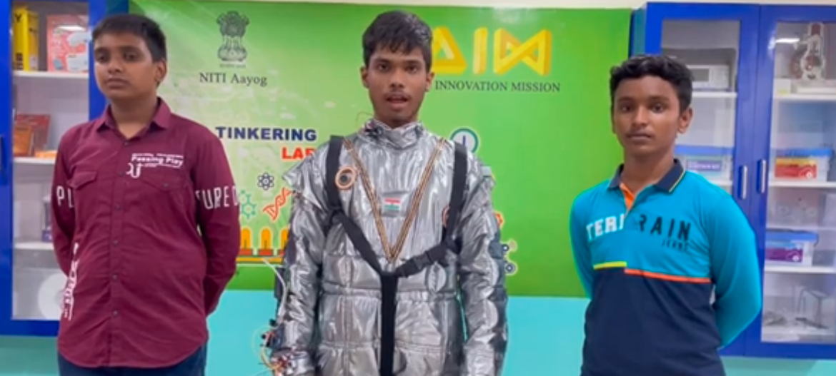
For a project resembling a smart space suit equipped with various sensors and actuators, the integrated system involving Arduino, NodeMCU, and multiple sensors can be designed to monitor environmental conditions and the wearer’s health, while providing necessary alerts and connectivity. Here is a detailed description of how each component fits into the space suit project.
The smart space suit is designed to monitor vital environmental parameters and the astronaut’s health, providing real-time feedback and alerts to ensure safety and optimal performance in space.

Component Required:
- Arduino Uno
- NodeMCU
- Soil Moisture Sensor
- Buzzer
- Metal Detector Sensor
- LEDs
- Ultrasonic Sensor
- 16×2 I2C LCD
- PIR Sensors
- Sound Sensor
- Gas Sensor
- Touch Sensor
- Pulse Sensor
- Humidity Sensor
- Pressure Sensor
Circuit Connection:
Arduino Uno:
- The main microcontroller is responsible for interfacing with most sensors and actuators.
- Handles the primary data acquisition and control tasks.
NodeMCU:
- Provides Wi-Fi connectivity for remote monitoring and data logging.
- Communicates with the Arduino via serial communication to offload data and manage internet connectivity.
Sensors and Actuators:
Soil Moisture Sensor
- Connection:
- VCC to 5V
- GND to GND
- Analog Output to A0
- Function: Monitors the internal humidity of the suit.
- Action: Triggers a buzzer if the humidity level exceeds a certain threshold.
Buzzer:
- Connection:
- Positive to Digital Pin 2
- Negative to GND
- Function: Alerts the astronaut in case of critical conditions such as high humidity, gas detection, or proximity alerts.
Metal Detector Sensor:
- Connection:
- VCC to 5V
- GND to GND
- Digital Output to Digital Pin 3
- Function: Detects metallic objects in the suit’s vicinity.
- Action: Lights up LED1 when a metallic object is detected.
LEDs:
- Connection:
- LED1: Anode to Digital Pin 4
- Cathode to GND via 220Ω resistor
- LED2: Anode to Digital Pin 5, Cathode to GND via 220Ω resistor
- Function: Visual indicators for various alerts.
- Action: LED1 for metal detection; LED2 for proximity alerts from the ultrasonic sensor.
Ultrasonic Sensor:
- Connection:
- VCC to 5V
- GND to GND
- Trig to Digital Pin 6
- Echo to Digital Pin 7
- Function: Measures the distance to nearby objects.
- Action: Lights up LED2 when an object is closer than a specified distance, alerting the astronaut of potential collisions.
16×2 I2C LCD:
- Connection:
- SDA to A4
- SCL to A5
- VCC to 5V
- GND to GND
- Function: Displays real-time sensor data and alerts.
PIR Sensors:
- Connection:
- PIR1: VCC to 5V)
- GND to GND (Arduino), Output to Digital Pin 8 (Arduino)
- PIR2: VCC to 5V (Arduino), GND to GND (Arduino), Output to Digital Pin 9 (Arduino)
- Function: Detects motion around the astronaut
Sound Sensor:
- Connection:
- VCC to 5V (Arduino)
- GND to GND (Arduino)
- Analog Output to A1 (Arduino)
- Function: Monitors ambient noise levels inside the suit.
Gas Sensor:
- Connection:
- VCC to 5V (Arduino)
- GND to GND (Arduino)
- Analog Output to A2 (Arduino)
- Function: Detects hazardous gases within the suit.
Touch Sensor:
- Connection:
- VCC to 5V (Arduino)
- GND to GND (Arduino)
- Digital Output to Digital Pin 10 (Arduino)
- Function: Detects touch input for control purposes.
Pulse Sensor:
- Connection:
- VCC to 5V (Arduino)
- GND to GND (Arduino)
- Analog Output to A3 (Arduino)
- Function: Monitors the astronaut’s heart rate.
Humidity Sensor:
- Connection:
- VCC to 5V (Arduino)
- GND to GND (Arduino)
- Data to Digital Pin 11 (Arduino)
- Function: Measures humidity levels within the suit.
Pressure Sensor:
- Connection:
- VCC to 5V (Arduino)
- GND to GND (Arduino)
- Data to Analog Pin A4 (Arduino)
- Function: Measures the atmospheric pressure within the suit.
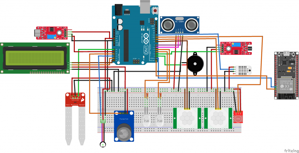
The circuit connection is given below:
Serial Communication:
Between Arduino and NodeMCU:
- TX (NodeMCU) to RX (Arduino Pin 0)
- RX (NodeMCU) to TX (Arduino Pin 1)
Functionality Overview:
Data Collection:
- The Arduino collects data from all connected sensors.
- Critical alerts (e.g., high humidity, gas detection) trigger the buzzer and LEDs.
Data Transmission:
- The Arduino sends sensor data to the NodeMCU via serial communication.
Remote Monitoring:
- The NodeMCU connects to a Wi-Fi network and can transmit data to a remote server for monitoring.
- This allows ground control to keep track of the astronaut’s suit conditions in real-time.
User Interface:
- The 16×2 I2C LCDs real-time data and alerts for the astronaut.
The code is given below:
Code for Arduino Uno:
#define SOIL_MOISTURE_PIN A0
#define METAL_DETECTOR_PIN 3
#define ULTRASONIC_TRIG_PIN 6
#define ULTRASONIC_ECHO_PIN 7
#define BUZZER_PIN 2
#define LED1_PIN 4
#define LED2_PIN 5

void setup() {
  pinMode(BUZZER_PIN, OUTPUT);
  pinMode(LED1_PIN, OUTPUT);
  pinMode(LED2_PIN, OUTPUT);
  pinMode(METAL_DETECTOR_PIN, INPUT);
  pinMode(ULTRASONIC_TRIG_PIN, OUTPUT);
  pinMode(ULTRASONIC_ECHO_PIN, INPUT);
  Serial.begin(9600);
}

void loop() {
  // Soil Moisture Sensor
  int soilMoistureValue = analogRead(SOIL_MOISTURE_PIN);
  if (soilMoistureValue < 300) { // Adjust threshold as needed
    digitalWrite(BUZZER_PIN, HIGH);
  } else {
    digitalWrite(BUZZER_PIN, LOW);
  }

  // Metal Detector Sensor
  if (digitalRead(METAL_DETECTOR_PIN) == HIGH) {
    digitalWrite(LED1_PIN, HIGH);
  } else {
    digitalWrite(LED1_PIN, LOW);
  }

  // Ultrasonic Sensor
  digitalWrite(ULTRASONIC_TRIG_PIN, LOW);
  delayMicroseconds(2);
  digitalWrite(ULTRASONIC_TRIG_PIN, HIGH);
  delayMicroseconds(10);
  digitalWrite(ULTRASONIC_TRIG_PIN, LOW);

  long duration = pulseIn(ULTRASONIC_ECHO_PIN, HIGH);
  int distance = duration * 0.034 / 2; // Distance in cm

  if (distance < 50) { // Adjust threshold as needed
    digitalWrite(LED2_PIN, HIGH);
  } else {
    digitalWrite(LED2_PIN, LOW);
  }

  // Send data to NodeMCU
  Serial.print("Soil Moisture: ");
  Serial.print(soilMoistureValue);
  Serial.print(", Metal Detector: ");
  Serial.print(digitalRead(METAL_DETECTOR_PIN));
  Serial.print(", Distance: ");
  Serial.println(distance);

  delay(1000); // Send data every second
}
Code for NodeMCU:
#include <ESP8266WiFi.h>

const char* ssid = "your_SSID";
const char* password = "your_PASSWORD";

void setup() {
  Serial.begin(9600); // Start the Serial communication
  WiFi.begin(ssid, password); // Connect to Wi-Fi

  while (WiFi.status() != WL_CONNECTED) {
    delay(1000);
    Serial.println("Connecting to WiFi...");
  }

  Serial.println("Connected to WiFi");
}

void loop() {
  if (Serial.available() > 0) {
    String data = Serial.readString();
    Serial.println("Received from Arduino: " + data);

    // Example: send data to a server
    // if(WiFi.status() == WL_CONNECTED){
    //   WiFiClient client;
    //   if (client.connect("server_address", server_port)) {
    //     client.println(data);
    //     client.stop();
    //   }
    // }
  }
}
Application:
Extraterrestrial Exploration:
· Suitable for missions to the Moon, Mars, and other celestial bodies.
Space Tourism:
· Providing affordable space suits for commercial space tourism companies.
Research and Development:
· Used in scientific research and testing in simulated space environments on Earth.