Components Needed:
- 2.2kΩ Resistor
- 2N2222A NPN Transistor
- A Switch
- Copper Wire
- Aluminum Foil
- Battery (e.g., 9V battery)
Circuit Explanation and Connections:
Transmitter Circuit:
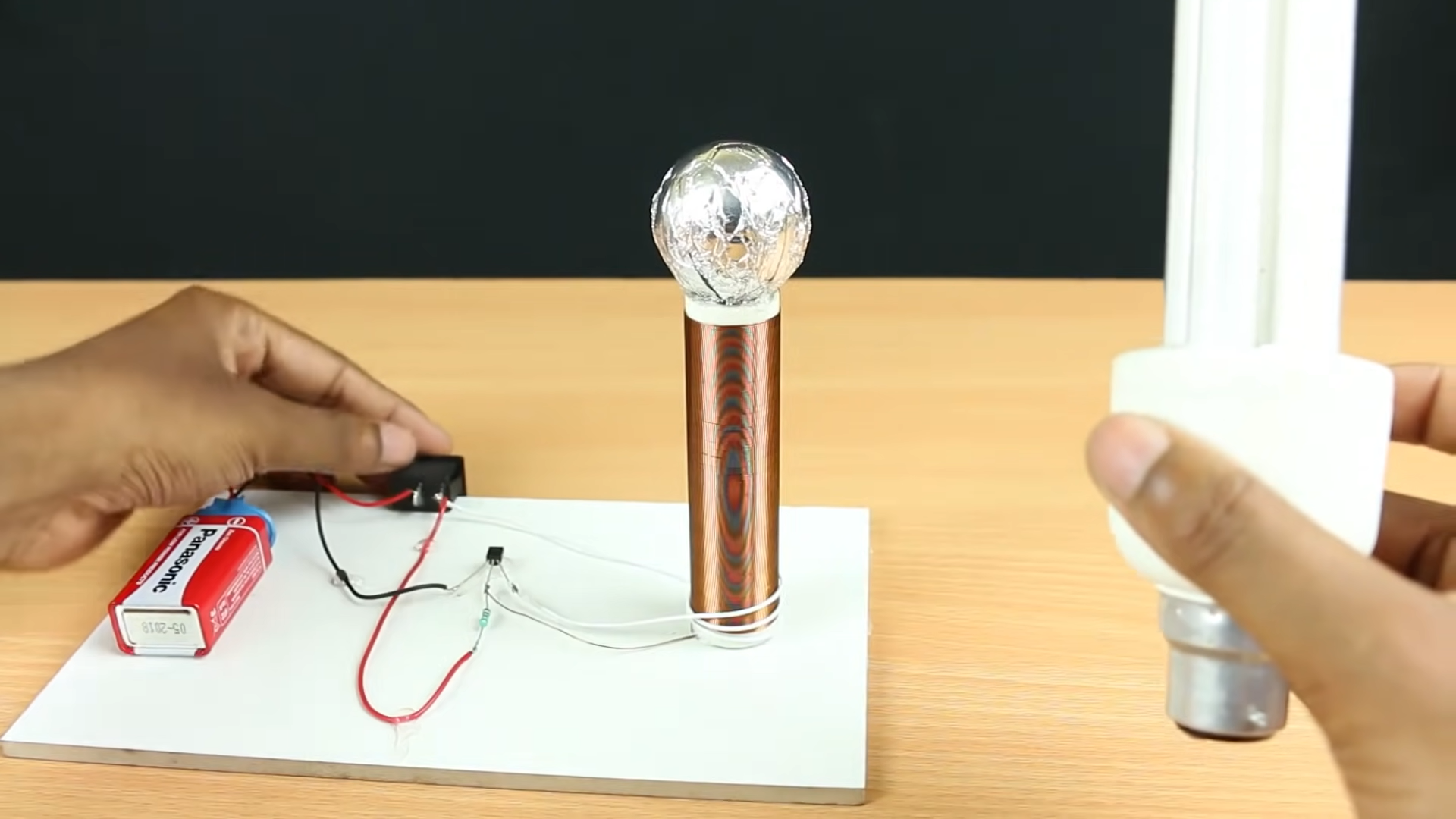
- Transistor (2N2222A):
- The 2N2222A transistor will act as a switch to control the power flow through the circuit. It has three leads: collector (C), base (B), and emitter (E).
- Connect the collector (C) of the transistor to one end of the copper wire.
- Connect the other end of the copper wire to the positive terminal of the battery (e.g., 9V battery).
- Resistor (2.2kΩ):
- Connect one leg of the 2.2kΩ resistor to the base (B) of the transistor.
- Connect the other leg of the resistor to the negative terminal of the battery (ground).
- Aluminum Foil:
- Place a piece of aluminum foil near the emitter (E) of the transistor. This foil acts as the “antenna” or radiator for the wireless transmission of power.
- Battery:
- Connect the negative terminal of the battery to ground (common ground with the transistor and resistor).
Receiver Circuit (not detailed here, but typically involves a coil to receive the transmitted power):
- On the receiving side, you would typically have another coil or a setup to receive the power transmitted wirelessly from the aluminum foil antenna. This setup could involve another transistor and a load (like an LED) that gets powered wirelessly.
How It Works:
- When the circuit is powered on, the 2N2222A transistor acts as a switch controlled by the base current (through the 2.2kΩ resistor).
- The transistor allows current to flow through the copper wire, creating a changing magnetic field around the wire.
- This changing magnetic field induces a current in the nearby aluminum foil (acting as an antenna), generating a voltage that can be used to power a load (on the receiver side).
