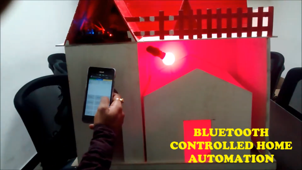
Wireless home automation project involves creating a Bluetooth-operated system using an Arduino Uno, two single-channel relays, an HC-05 Bluetooth module, and two bulbs with holders. The Arduino Uno serves as the central microcontroller, managing the entire operation. The HC-05 Bluetooth module allows the Arduino to communicate wirelessly with a smartphone. When a command is sent from the smartphone, the Arduino receives the signal through the HC-05 module and processes it. The Arduino then activates or deactivates the relays based on the received command. Each relay controls the power to a bulb, enabling it to turn on or off. This setup demonstrates a basic home automation system where you can control lighting remotely using Bluetooth technology. Wireless home automation project is straightforward and serves as an excellent introduction to integrating Bluetooth communication with micro-controller-based automation. It can be expanded to include more devices and sensors, providing a scalable solution for smart home applications.
Components used in this project are:
- Arduino UNO with cable
- Single Channel Relay x 2
- Bluetooth module HC-05
- Bulb x 2
- Bulb Holder x 2
- Electric Wire
- Male to Female jumper wires x 10
Featured Image:
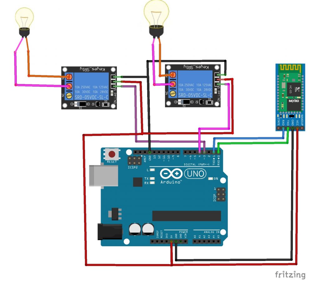
Pin Connection:
Arduino Uno:
- Digital Pin 3: Connected to Relay 1 Control Pin
- Digital Pin 4: Connected to Relay 2 Control Pin
- 5V Pin: Connected to VCC of HC-05 Bluetooth Module
- GND Pin: Connected to GND of HC-05 Bluetooth Module
HC-05 Bluetooth Module:
- VCC: Connected to 5V Pin of Arduino Uno
- GND: Connected to GND Pin of Arduino Uno
- TXD: Connected to RX Pin (Digital Pin 0) of Arduino Uno through a voltage divider (optional for level shifting)
- RXD: Connected to TX Pin (Digital Pin 1) of Arduino Uno
Relay Modules (each relay):
- VCC: Connected to 5V Pin of Arduino Uno (for powering the relay module)
- GND: Connected to GND Pin of Arduino Uno
- IN1 (or Signal Pin): Connected to Digital Pin 3 (for Relay 1) and Digital Pin 4 (for Relay 2) of Arduino Uno
Bulb with Holder:
- One terminal of the bulb holder connected to the Common (COM) terminal of each relay module.
- The other terminal of the bulb holder connected to the Normally Open (NO) terminal of each relay module
App Link for Controlling through Mobile :- https://play.google.com/store/apps/details?id=com.broxcode.arduinobluetoothfree&hl=en
After installing the app follow the steps below:
Step 1: Turn ON bluetooth of the device and pair HC-05. Enter the pair pin – 1234.
Step 2: After successfully paired by following the above step, open the app and click on this button.
Step 3 : Then, Click on HC-05
Step 4 : After Successfully connected to HC-05, Click on this button and control.
Circuit Diagram:
Code:
char val;

#define relay1 3
#define relay2 4

void setup() {

  pinMode(relay1, OUTPUT);
  pinMode(relay2, OUTPUT);
  Serial.begin(9600);
  digitalWrite(relay1, LOW);
  digitalWrite(relay2, LOW);
}

void loop() {

  if (Serial.available()) {
    val = Serial.read();
    Serial.println(val);
  }
  if (val == 'A') {
    digitalWrite(relay2, HIGH);

  }
  if (val == 'B') {
    digitalWrite(relay2, HIGH);

  }
  if (val == 'C') {
    digitalWrite(relay2, HIGH);
    digitalWrite(relay2, HIGH);
  }
  if (val == 'D') {
    digitalWrite(relay1, LOW);
    digitalWrite(relay2, LOW);
  }

  delay(100);

}


