The Vehicle Speed Limiter (VSL) project is designed to significantly enhance road safety by implementing an intelligent speed control mechanism in vehicles. This system utilizes various components including an Arduino Uno, DC Motor, Ultrasonic Sensor, RF Receiver (RX), and RF Transmitter (TX) to effectively regulate vehicle speed based on dynamic road conditions, set speed limits, and the proximity of obstacles. This comprehensive approach ensures that vehicles maintain safe speeds, reducing the likelihood of accidents and promoting responsible driving habits.
Components Used:
- Arduino Uno: Serves as the central control unit for processing sensor data and controlling the speed limiter system.
- DC Motor: Controls the throttle or speed of the vehicle, adjusting it based on the signals received from the Arduino.
- Ultrasonic Sensor: Measures the distance between the vehicle and obstacles, providing real-time data for speed adjustment.
- RF Receiver (RX): Receives wireless signals from the RF Transmitter for communication and control purposes.
- RF Transmitter (TX): Sends control signals wirelessly to the RF Receiver, allowing for remote speed regulation.
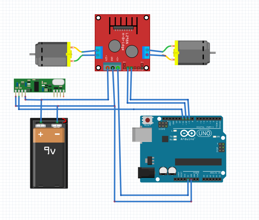
CIRCUIT FOR RX
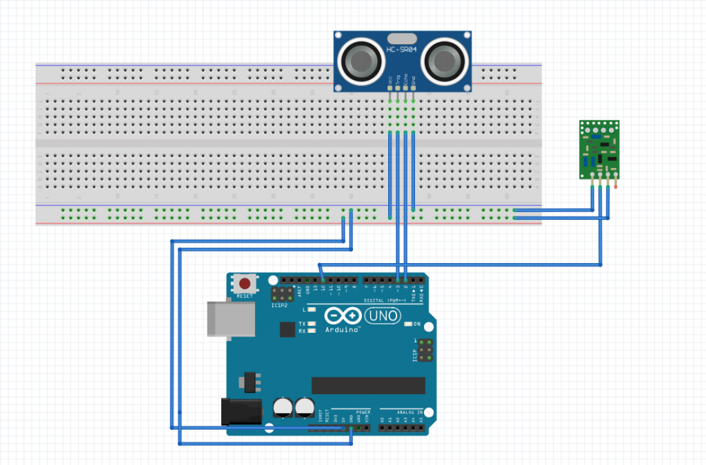
CIRCUIT FOR TX
CODE FOR RX
#include <VirtualWire.h>

// Constants for DC motor control
#define MOTOR_PIN_1 9        // Pin connected to DC motor 1 control
#define MOTOR_PIN_2 10       // Pin connected to DC motor 2 control
#define MAX_SPEED 255        // Maximum speed of the motor (PWM value)

// RF Module constants
#define RF_RX_PIN 11         // Arduino pin connected to RF receiver

void setup() {
  Serial.begin(9600);    // Initialize serial communication for debugging
  pinMode(MOTOR_PIN_1, OUTPUT); // Set motor 1 pin as output
  pinMode(MOTOR_PIN_2, OUTPUT); // Set motor 2 pin as output

  vw_set_rx_pin(RF_RX_PIN); // Set RF receiver pin
  vw_setup(2000);        // Bits per second
  vw_rx_start();         // Start the receiver
}

void loop() {
  // Check for RF commands
  uint8_t buf[VW_MAX_MESSAGE_LEN];
  uint8_t buflen = VW_MAX_MESSAGE_LEN;

  if (vw_get_message(buf, &buflen)) { // Non-blocking check for RF messages
    int command = atoi((char *)buf); // Convert received message to integer

    // Adjust motor speeds based on RF command
    if (command == 1) {
      // Reduce motor speeds
      int reduced_speed_1 = constrain(analogRead(MOTOR_PIN_1) - 50, 0, MAX_SPEED); // Reduce speed by 50 PWM units
      int reduced_speed_2 = constrain(analogRead(MOTOR_PIN_2) - 50, 0, MAX_SPEED); // Reduce speed by 50 PWM units
      analogWrite(MOTOR_PIN_1, reduced_speed_1);
      analogWrite(MOTOR_PIN_2, reduced_speed_2);
      Serial.print("Reduced Speed 1: ");
      Serial.print(reduced_speed_1);
      Serial.print(", Reduced Speed 2: ");
      Serial.println(reduced_speed_2);
    } else {
      // Maintain normal speeds
      analogWrite(MOTOR_PIN_1, MAX_SPEED); // Set motor 1 to maximum speed
      analogWrite(MOTOR_PIN_2, MAX_SPEED); // Set motor 2 to maximum speed
      Serial.println("Normal Speed");
    }
  }

  delay(500); // Delay between checks
}
CODE FOR TX
#include <NewPing.h>
#include <VirtualWire.h>

// Constants for ultrasonic sensor
#define TRIGGER_PIN 3        // Arduino pin tied to trigger pin on ultrasonic sensor
#define ECHO_PIN 2        // Arduino pin tied to echo pin on ultrasonic sensor
#define MAX_DISTANCE 200     // Maximum distance we want to ping for (in centimeters)

// RF Module constants
#define RF_TX_PIN 12         // Arduino pin connected to RF transmitter

// Global variables
NewPing sonar(TRIGGER_PIN, ECHO_PIN, MAX_DISTANCE); // NewPing object to handle ultrasonic sensor

void setup() {
  Serial.begin(9600);    // Initialize serial communication for debugging
  vw_set_tx_pin(RF_TX_PIN); // Set RF transmitter pin
  vw_setup(2000);        // Bits per second
}

void loop() {
  // Measure distance from ultrasonic sensor
  unsigned int distance = sonar.ping_cm();

  // Prepare command based on distance
  int command = (distance <= 30) ? 1 : 0; // Command 1 if distance <= 30 cm, otherwise 0

  // Transmit command via RF module
  vw_send((uint8_t *)&command, sizeof(command));
  vw_wait_tx(); // Wait until the whole message is gone

  delay(500); // Delay between transmissions
}
How It Works:
- Speed Monitoring: The Ultrasonic Sensor continuously measures the distance between the vehicle and nearby obstacles, such as other vehicles or speed limit signs.
- Speed Regulation: The Arduino calculates and adjusts the vehicle’s speed by controlling the DC Motor based on the distance data received.
- Wireless Control: The RF Transmitter wirelessly sends control signals to the RF Receiver, enabling remote communication for speed limit adjustments and system activation.
Benefits:
- Enhanced Safety: Prevents vehicles from exceeding speed limits, reducing the risk of accidents and promoting safer driving practices.
- Compliance: Ensures vehicles adhere to speed regulations and restrictions imposed in specific areas or road conditions.


