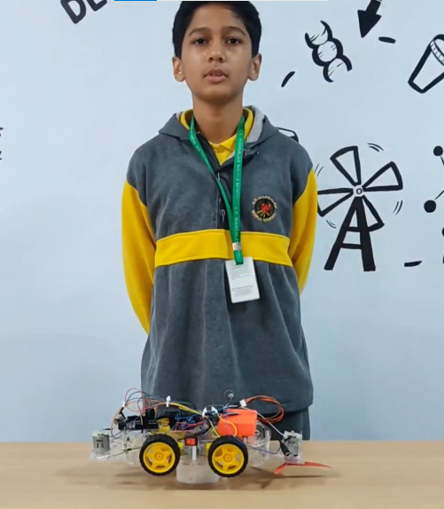
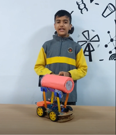
The Smart Washroom project is designed to tackle common issues in public and private washrooms, such as unauthorized access, vandalism, and the spread of germs due to frequent touching of surfaces. Public and shared washrooms often face these problems, making traditional lock-and-key mechanisms are unhygienic. There is a need for a more efficient and sanitary solution. By integrating an RFID system with an Arduino UNO microcontroller and a servomotor, this project offers a high-tech solution to improve security, cleanliness, and user experience.
Components Required:
- Arduino UNO
- RFID Reader Module
- RFID Cards/Tags
- Servomotor
- Breadboard
- Jumper Wires
Components Description:
- Arduino UNO: A microcontroller board that processes inputs and controls outputs, acting as the system’s brain.
- RFID Reader Module: Reads unique IDs from RFID cards or tags, enabling user authentication.
- RFID Cards/Tags: Each card or tag has a unique ID used to grant or deny access to the washroom.
- Servomotor: Mechanically controls the door lock based on signals from the Arduino.
- Breadboard: Provides a platform for constructing and testing the circuit without soldering.
- Jumper Wires: Connect various components on the breadboard and Arduino.
Circuit Connection:
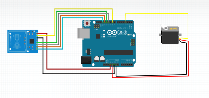
- RFID Reader Module:
- VCC: Connect to Arduino 3.3V
- GND: Connect to Arduino GND
- SDA (SS): Connect to Arduino Digital Pin 10
- SCK: Connect to Arduino Digital Pin 13
- MOSI: Connect to Arduino Digital Pin 11
- MISO: Connect to Arduino Digital Pin 12
- RST: Connect to Arduino Digital Pin 9
- Servo Motor:
- Signal Pin: Connect to Arduino Digital Pin 3
- Power (VCC): Connect to Arduino 5V
- Ground (GND): Connect to Arduino GND
Steps:
- Power Connections:
- Connect the VCC pin of the RFID Reader to the 3.3V pin on the Arduino.
- Connect the GND pin of RFID Reader to one of the GND pins on the Arduino.
- Connect the power pin (usually red wire) of the servo motor to the 5V pin on the Arduino.
- Connect the ground pin (usually black wire) of the servo motor to a GND pin on the Arduino.
- SPI Communication Setup:
- Connect the SDA (SS) pin of the Reader to Digital Pin 10 on the Arduino.
- Connect the SCK pin of the RFID Reader to Digital Pin 13 on the Arduino.
- Connect the MOSI pin of the RFID Reader to Digital Pin 11 on the Arduino.
- Connect the MISO pin of the RFID Reader to Digital Pin 12 on the Arduino.
- Connect the RST pin of the RFID Reader to Digital Pin 9 on the Arduino.
- Servo Motor Connection:
- Connect the signal pin of the servo motor to Digital Pin 3 on the Arduino.
- Program the Arduino:
- Upload the provided code to the Arduino UNO using the Arduino IDE.
#include <SPI.h>
#include <MFRC522.h>
#include <Servo.h>


#define SS_PIN 10
#define RST_PIN 9

#define SERVO_PIN 3
Servo myservo;

#define ACCESS_DELAY 2000
#define DENIED_DELAY 1000
MFRC522 mfrc522(SS_PIN, RST_PIN);   // Create MFRC522 instance.

void setup()
{
  Serial.begin(9600);   // Initiate a serial communication
  SPI.begin();          // Initiate  SPI bus
  mfrc522.PCD_Init();   // Initiate MFRC522

  myservo.attach(SERVO_PIN);
  myservo.write( 70 );
  delay(7500);
  myservo.write( 0 );
  Serial.println("Put your card to the reader...");
  Serial.println();

}
void loop()
{
  // Look for new cards
  if ( ! mfrc522.PICC_IsNewCardPresent())
  {
    return;
  }
  // Select one of the cards
  if ( ! mfrc522.PICC_ReadCardSerial())
  {
    return;
  }
  //Show UID on serial monitor
  Serial.print("UID tag :");
  String content= "";
  byte letter;
  for (byte i = 0; i < mfrc522.uid.size; i++)
  {
     Serial.print(mfrc522.uid.uidByte[i] < 0x10 ? " 0" : " ");
     Serial.print(mfrc522.uid.uidByte[i], HEX);
     content.concat(String(mfrc522.uid.uidByte[i] < 0x10 ? " 0" : " "));
     content.concat(String(mfrc522.uid.uidByte[i], HEX));
  }
  Serial.println();
  Serial.print("Message : ");
  content.toUpperCase();
  if (content.substring(1) == "69 C8 E2 2A") //change here the UID of the card
  {
    Serial.println("Authorized access");
    Serial.println();
   myservo.write( 70 );
 delay(7500);
  myservo.write( 0 );

  }

 else   {
    Serial.println(" Access denied");


    delay(DENIED_DELAY);


  }
}

