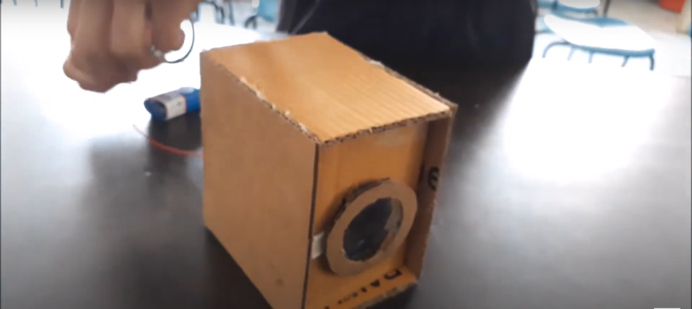
The Smart Guard Wallet is an innovative, secure wallet utilizing an Arduino microcontroller, buzzer, and RFID technology. It includes two RFID cards: one for the authorized user, preventing the buzzer from sounding, and another that triggers the alarm if someone else tries to take the wallet. The Arduino processes RFID inputs and controls the buzzer, ensuring unauthorized access attempts are immediately met with a loud alarm. Compact and user-friendly, the Smart Guard Wallet provides a reliable way to protect your valuables in any situation.
Components:
- Arduino Microcontroller – 1
- RFID Module (e.g., MFRC522) – 1
- Buzzer – 1
- RFID Cards – 2 (1 authorized, 1 unauthorized)
- Battery or Power Supply – 1
- Jumper Wires – Several
- Small Breadboard or PCB – 1 (optional)
- Enclosure – 1 (optional)
Connections:
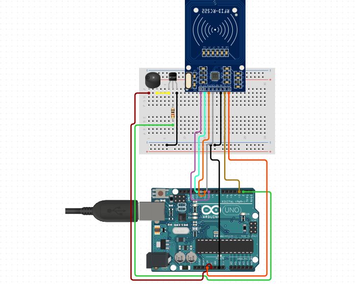
Arduino Microcontroller:
- Connect VCC to 5V or 3.3V power source.
- Connect GND to ground.
- Utilize digital pins for interfacing with other components.
RFID Module (e.g., MFRC522):
- SPI Connection:
- Connect VCC to 3.3V on Arduino.
- Connect GND to GND on Arduino.
- Connect RST to digital Pin 3.
- Connect IRQ (if applicable) to digital pin.
- Connect SDA (SDI) to digital Pin 10
- Connect SCK to digital pin.
- Connect MISO to digital pin.
- Connect MOSI to digital pin.
Buzzer:
- Connect one terminal to digital output Pin 2.
- Connect the other terminal to GND through a current-limiting resistor if needed.
RFID Cards:
- Place within detection range of RFID module.
Battery or Power Supply:
- Connect to appropriate power input (5V or 3.3V) on Arduino.
Jumper Wires:
- Use to establish connections between Arduino and components based on specifications.
Small Breadboard or PCB (optional):
- Use for prototyping and organizing connections.
#include <SPI.h>
#include <MFRC522.h>

#define SS_PIN 10
#define RST_PIN 3
#define BUZZER_PIN 2

MFRC522 mfrc522(SS_PIN, RST_PIN);

const byte authorizedUID[4] = {0xDE, 0xAD, 0xBE, 0xEF}; // Replace with the UID of your authorized RFID card

void setup() {
  Serial.begin(9600);
  SPI.begin();
  mfrc522.PCD_Init();
  pinMode(BUZZER_PIN, OUTPUT);
  digitalWrite(BUZZER_PIN, LOW);
}

void loop() {
  if (!mfrc522.PICC_IsNewCardPresent() || !mfrc522.PICC_ReadCardSerial()) {
    return;
  }

  byte readUID[4];
  for (byte i = 0; i < 4; i++) {
    readUID[i] = mfrc522.uid.uidByte[i];
  }

  if (isAuthorized(readUID)) {
    digitalWrite(BUZZER_PIN, LOW);
  } else {
    digitalWrite(BUZZER_PIN, HIGH);
  }

  delay(1000); // Beep duration
  digitalWrite(BUZZER_PIN, LOW);

  mfrc522.PICC_HaltA();
  mfrc522.PCD_StopCrypto1();
}

bool isAuthorized(byte *uid) {
  for (byte i = 0; i < 4; i++) {
    if (uid[i] != authorizedUID[i]) {
      return false;
    }
  }
  return true;
}