Project Description:
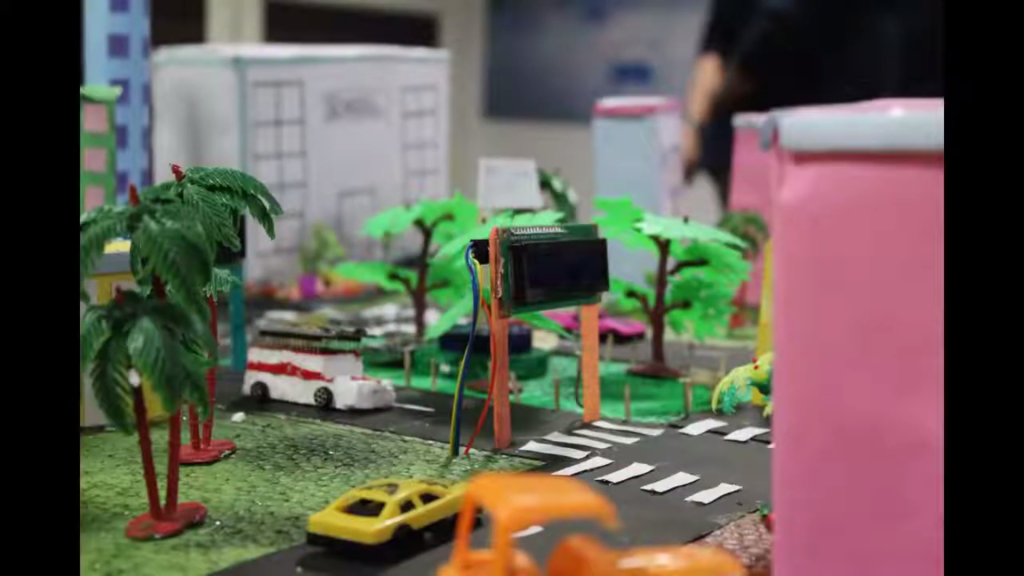
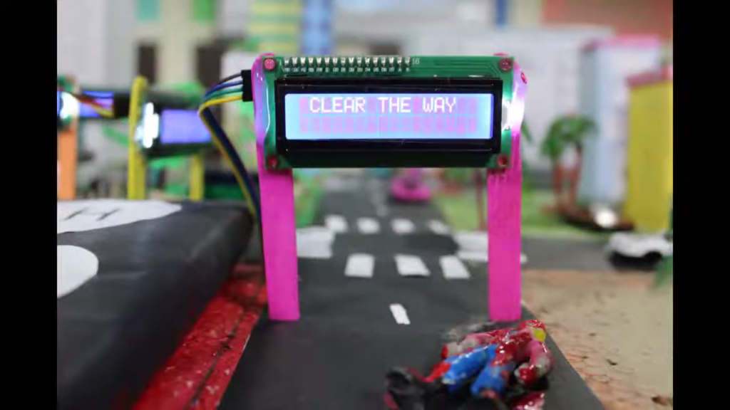
This project focuses on creating a smart traffic system to clear the way for ambulances using two ESP32 modules. One ESP32 module acts as a transmitter installed in the ambulance, sending a signal when the ambulance is approaching. The second ESP32 module acts as a receiver installed at the traffic signal, which upon receiving the signal, displays the message “CLEAR AREA” on three LCD screens to alert vehicles to make way for the ambulance. This system aims to reduce the response time for emergency services and save lives by ensuring that ambulances can move through traffic more quickly and efficiently.
Components Required:
- ESP32 modules with cable x 2
- 16×2 LCD I2C displays x 3
- Jumper wires – Female to Female x 4
– Male to Male x 4
– Male to Female x 12 - Breadboard small
- Lithium-ion battery 3.7v x 3
- Lithium-ion Battery holder x 1
Learning Outcomes
- Wireless Communication: Understand how to set up wireless communication between two ESP32 modules using ESP-NOW.
- I2C Communication: Learn how to interface multiple I2C devices (LCD displays) with the ESP32.
- Embedded Systems: Gain experience in integrating various hardware components and writing embedded C/C++ code to create functional systems.
IMAGE:

Connections:
Master ESP32
The transmitting ESP32 does not need to connect to any additional hardware for this example. It will send a signal wirelessly to the receiving ESP32.
Slave ESP32
The receiving ESP32 is connected to the three LCD I2c displays.
Connections for each I2C LCD:
- VCC to 3.3V (ESP32)
- GND to GND (ESP32)
- SDA to GPIO 21 (ESP32)
- SCL to GPIO 22 (ESP32)
CIRCUIT DIAGRAM:
TRANSMITTER ESP:
RECEIVER ESP:
CODE:
CODE TO FIND THE MAC ADDRESS OF THE RECEIVER ESP:
First, run this code in the receiver ESP to get the Mac address and use that address in the transmitter transmitter code.
#include <WiFi.h>
#include <esp_wifi.h>

void readMacAddress(){
  uint8_t baseMac[6];
  esp_err_t ret = esp_wifi_get_mac(WIFI_IF_STA, baseMac);
  if (ret == ESP_OK) {
    Serial.printf("%02x:%02x:%02x:%02x:%02x:%02x\n",
                  baseMac[0], baseMac[1], baseMac[2],
                  baseMac[3], baseMac[4], baseMac[5]);
  } else {
    Serial.println("Failed to read MAC address");
  }
}

void setup(){
  Serial.begin(115200);

  WiFi.mode(WIFI_STA);
  WiFi.STA.begin();

  Serial.print("[DEFAULT] ESP32 Board MAC Address: ");
  readMacAddress();
}

void loop(){

}
TRANSMITTER ESP CODE:
#include <WiFi.h>
#include <esp_now.h>

// Replace with your network credentials
const char* ssid = "YOUR_SSID";
const char* password = "YOUR_PASSWORD";

// MAC Address of the receiver ESP32
uint8_t broadcastAddress[] = {0x24, 0x6F, 0x28, 0xAE, 0x8B, 0x70};

// Structure example to send data
typedef struct struct_message {
    char a[32];
} struct_message;

// Create a struct_message called myData
struct_message myData;

void setup() {
  Serial.begin(115200);

  // Set device as a Wi-Fi Station
  WiFi.mode(WIFI_STA);

  // Init ESP-NOW
  if (esp_now_init() != ESP_OK) {
    Serial.println("Error initializing ESP-NOW");
    return;
  }

  // Register peer
  esp_now_peer_info_t peerInfo;
  memcpy(peerInfo.peer_addr, broadcastAddress, 6);
  peerInfo.channel = 0;
  peerInfo.encrypt = false;

  // Add peer
  if (esp_now_add_peer(&peerInfo) != ESP_OK){
    Serial.println("Failed to add peer");
    return;
  }

  // Prepare message
  strcpy(myData.a, "Clear the area");
}

void loop() {
  // Send message via ESP-NOW
  esp_err_t result = esp_now_send(broadcastAddress, (uint8_t *) &myData, sizeof(myData));

  if (result == ESP_OK) {
    Serial.println("Sent with success");
  }
  else {
    Serial.println("Error sending the data");
  }

  delay(5000); // Send every 5 seconds
}
RECEIVER ESP CODE:
#include <Wire.h>
#include <LiquidCrystal_I2C.h>
#include <WiFi.h>
#include <esp_now.h>

// LCD address list
uint8_t lcdAddresses[] = {0x27, 0x26, 0x25, 0x24, 0x23};
LiquidCrystal_I2C lcd1(0x27, 16, 2);
LiquidCrystal_I2C lcd2(0x26, 16, 2);
LiquidCrystal_I2C lcd3(0x25, 16, 2);

// Structure example to receive data
typedef struct struct_message {
    char a[32];
} struct_message;

// Create a struct_message called incomingData
struct_message incomingData;

void setup() {
  Serial.begin(115200);

  // Initialize LCDs
  lcd1.init();
  lcd1.backlight();
  lcd2.init();
  lcd2.backlight();
  lcd3.init();
  lcd3.backlight();


  // Set device as a Wi-Fi Station
  WiFi.mode(WIFI_STA);

  // Init ESP-NOW
  if (esp_now_init() != ESP_OK) {
    Serial.println("Error initializing ESP-NOW");
    return;
  }

  // Register receive callback
  esp_now_register_recv_cb(OnDataRecv);
}

// Callback function executed when data is received
void OnDataRecv(const uint8_t * mac, const uint8_t *incomingData, int len) {
  memcpy(&incomingData, incomingData, sizeof(incomingData));

  // Print received data to Serial Monitor
  Serial.print("Bytes received: ");
  Serial.println(len);
  Serial.print("Message: ");
  Serial.println(incomingData.a);

  // Display message on LCDs
  lcd1.clear();
  lcd1.print(incomingData.a);
  lcd2.clear();
  lcd2.print(incomingData.a);
  lcd3.clear();
  lcd3.print(incomingData.a);

}

void loop() {
  // Nothing to do here
}


