Project Description:
This project aims to develop a home automation or automatic home monitoring system using ESP8266. In this project, we aim to use sensors and interface them with the ESP module to monitor the home. For example, we use a DHT-11 sensor for monitoring the temperature and humidity. Another sensor is MQ-2 for the detection of the leakage of LPG gas and triggers the alarm which is a buzzer in this case. We will also use Blynk app to monitor the activities on the mobile remotely.
Components Required:
- ESP 8266 with cable X 1
- GAS SENSOR MQ-2 X 1
- DHT-11 SENSOR X 1
- JUMPER WIRES – FEMALE TO FEMALE X 8
Learning Outcomes:
- Integration of different sensors
- Security of home
- Coding of ESP8266 and DIY project
Connections:
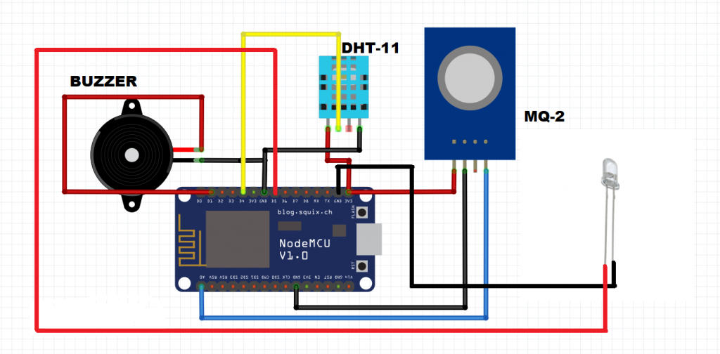
- Connections of buzzer with ESP:
- Connect the positive of buzzer to GPIO 20 that is D1 of ESP
- Connect the negative of the buzzer to GND of ESP
- Connections of MQ-2 with ESP:
- Connect the VCC of sensor to 3.3v of ESPConnect the GND of the sensor with the GND of the ESP
- Connect the A0 (analog pin) with the A0 of ESP
- Connection of DHT-11 with ESP:
- Connect the VCC of sensor to 3.3v of ESPConnect the GND of the sensor with the GND of the ESP
- Connect the signal pin D0 of sensor to the GPIO 17 that is D4 of ESP
- Connection of LED with ESP:
- Connect the positive of LED with GPIO 5 D5.
- Connect the negative of LED with the GND
NOTE: Before uploading and running the code IN ARDUINO IDE:
Go to > Sketch > Include Library > Manage Libraries… > Type the library name
OR Go to > Sketch > Include Library > Add .ZIP Library… download the zip library from the link given below.
DHT library – https://github.com/adafruit/DHT-sensor-library
BlynkSimpleEsp8266 library – https://github.com/blynkkk/blynk-library
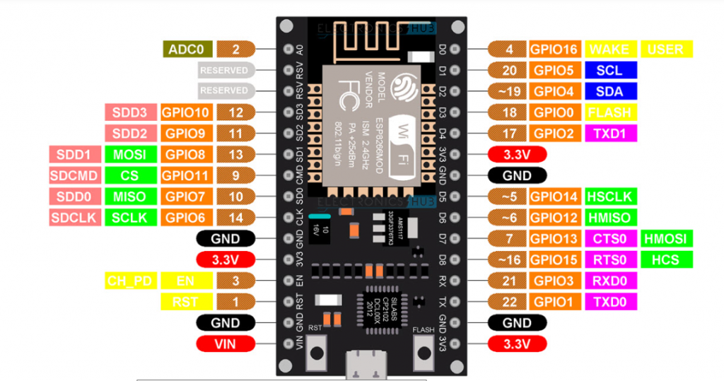
ESP 8266 Pin Diagram:
Circuit Diagram:
How to add the Node MCU board in Arduino IDE Step-By-Step Process:
Steps are as follows:
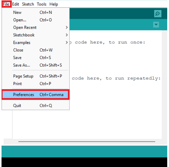
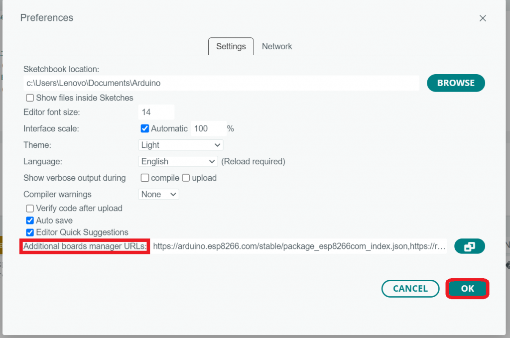
Step-1: In Arduino IDE Click on File > Preferences
Step-2: In Additional Board Manager URLs paste the link given below
link: https://arduino.esp8266.com/stable/package_esp8266com_index.json
and Click OK Button
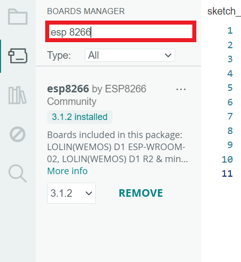
Step-3: In Arduino IDE
Go to Tools > Board >Boards Manager…
Search ESP8266 and install the ESP8266 by ESP8266 Community and Click INSTALL
Step-4: In Arduino IDE go to Tools > Board: > esp8266 > Select NodeMCU 1.0 (ESP-12E Module)
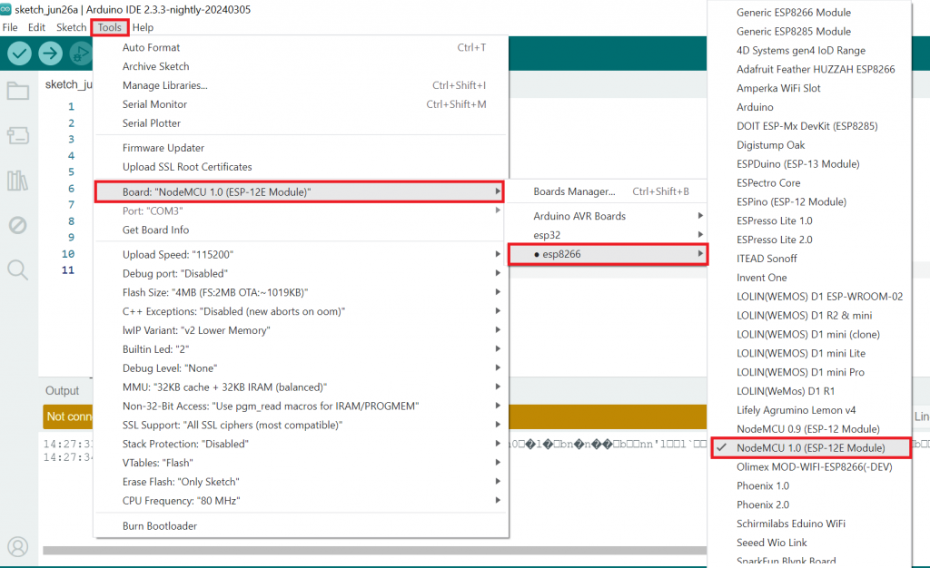
Step-5: Now you have sucessfully selected the board you can upload the code.
CODE:
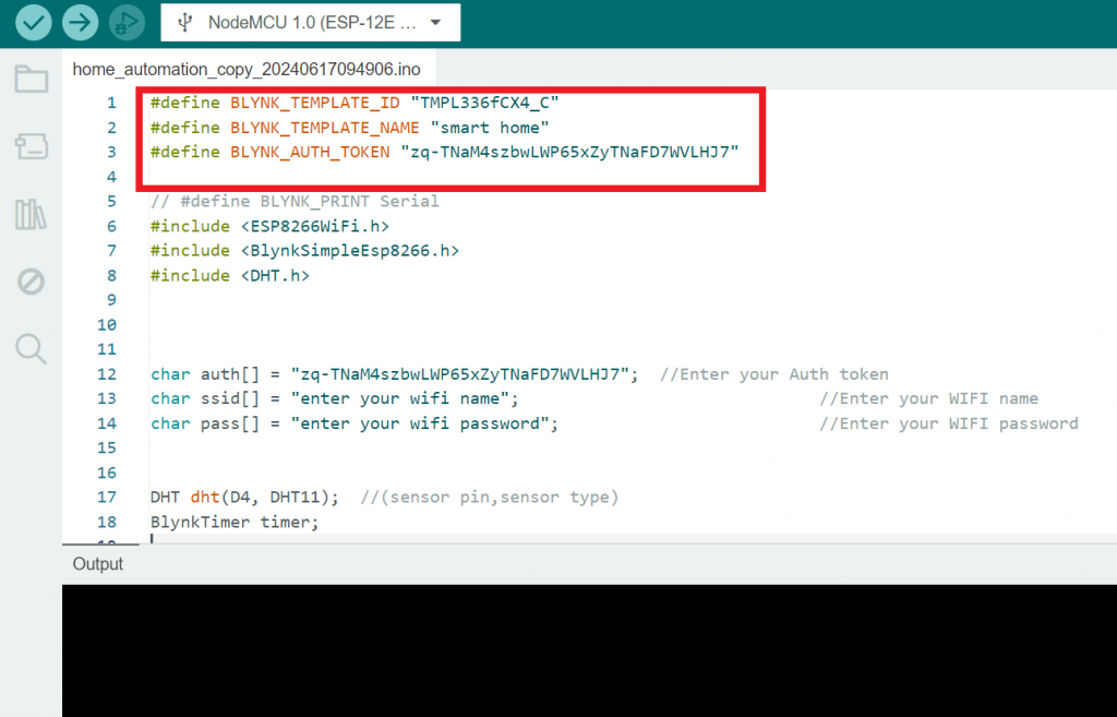
#define BLYNK_TEMPLATE_ID "TMPL3Jw-zcxaX"
#define BLYNK_TEMPLATE_NAME "SMART HOME"

#define BLYNK_PRINT Serial
#include <ESP8266WiFi.h>
#include <BlynkSimpleEsp8266.h>

// You should get Auth Token in the Blynk App.
// Go to the Project Settings (nut icon).
char auth[] = "e-gz9P4QhMJwpRQXkFH4XoGiLfVuV8_e";

// Your WiFi credentials.
// Set password to "" for open networks.
char ssid[] = "enter your wifi name";
char pass[] = "enter your wifi password";

// Define the GPIO pin where the LED is connected.
const int ledPin = D5;

#include <DHT.h>

DHT dht(D4, DHT11);  //(sensor pin, sensor type)
BlynkTimer timer;

#define Buzzer 1
#define MQ2 A0

void setup() {
  Serial.begin(9600);

  pinMode(Buzzer, OUTPUT);
  pinMode(ledPin, OUTPUT);
  Blynk.begin(auth, ssid, pass);
  dht.begin();
  timer.setInterval(1000L, gassensor);
  timer.setInterval(2000L, DHT11sensor);
}

void gassensor() {
  int value = analogRead(MQ2);
  Serial.println(value);
  value = map(value, 0, 1024, 0, 100);
  if (value <= 35) {
    digitalWrite(Buzzer, LOW);
  } else if (value > 35) {
    digitalWrite(Buzzer, HIGH);
  }
  Blynk.virtualWrite(V3, value);
}

void DHT11sensor() {
  float h = dht.readHumidity();
  float t = dht.readTemperature();

  if (isnan(h) || isnan(t)) {
    Serial.println("Failed to read from DHT sensor!");
    return;
  }

  Blynk.virtualWrite(V1, t);
  Blynk.virtualWrite(V2, h);
}


BLYNK_WRITE(V4) {
  int pinValue = param.asInt();  // Get value as integer

  // Ensure pinValue is either 0 or 1
  if (pinValue == 0 || pinValue == 1) {
    digitalWrite(ledPin, pinValue);  // Set LED state
  } else {
    Serial.println("Received invalid value for LED control");
  }
}


void loop() {

  Blynk.run();
  timer.run();
}
reference to Blynk app: https://blynk.io/
Step-By-Step process to make an application using Blynk:
STEP-1: Go to the browser and type Blynk IOT Platform app
sign up with your Mail ID
after signing up login with the same ID
you will get a screen to create a new template
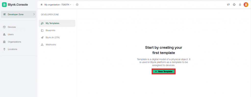
STEP-2: Click on create new template and give the name of your project.
Select the Hardware as ESP8266 and give a description that what this project do
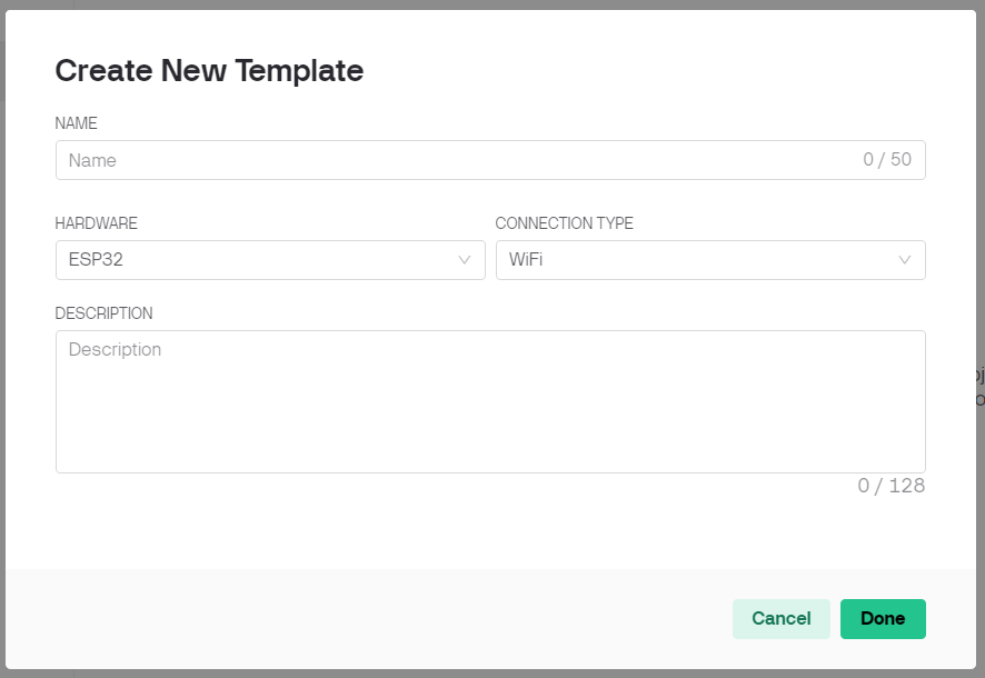
STEP-3: Click on Done and save
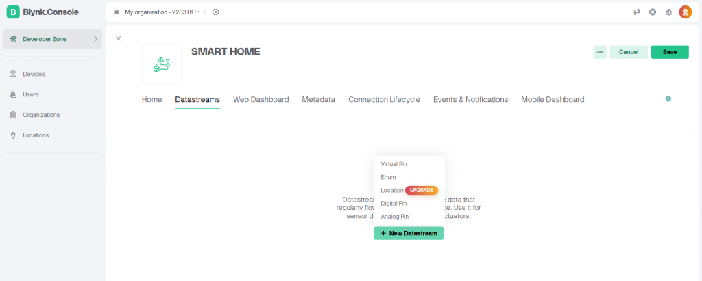
Go to Datastreams and click Edit option
Click on New Datastream and select Virtual Pin
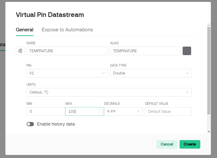
STEP-4: Give the name to the virtual pin example Temperature
Select Pin as V1
Select the UNITS as Celsius
Select the MIN as 0 and MAX as 100
Click on create
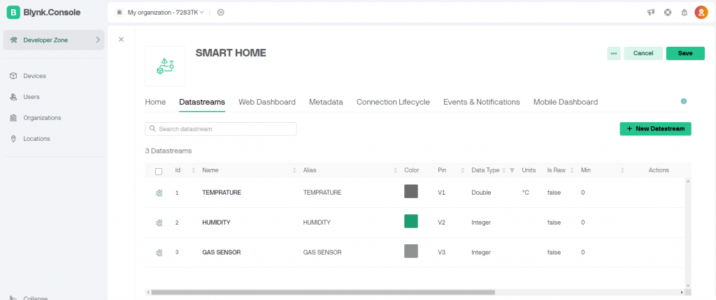
STEP-5: In same way create the virtuall pin v2 as humidity for humidity min value is 0 and max value is 100 Note: leave the unit as blank
and V3 as gas sensor for gas sensor min value is 0 and max value is 100 note: leave the unit as blank
and create a virtual pin as V4 for an LED.
After creating the virtual pins click save
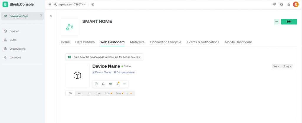
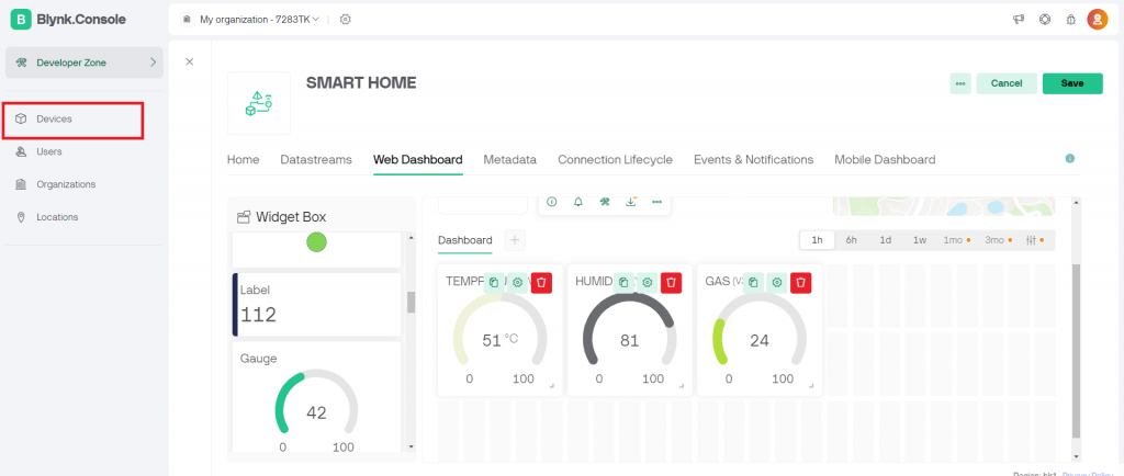
STEP-6 Go to Web Dashboard click Edit
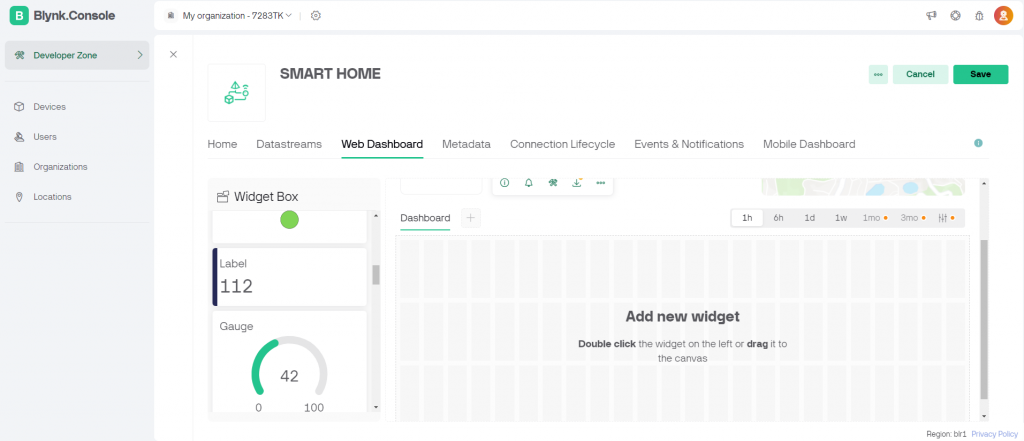
STEP-7: From widget box add gauge by double clicking or you can Drag and Drop the gauge.
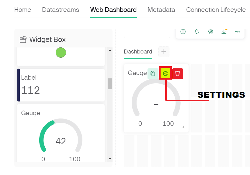
STEP-8: after adding the gauge click on the gauge settings symbol
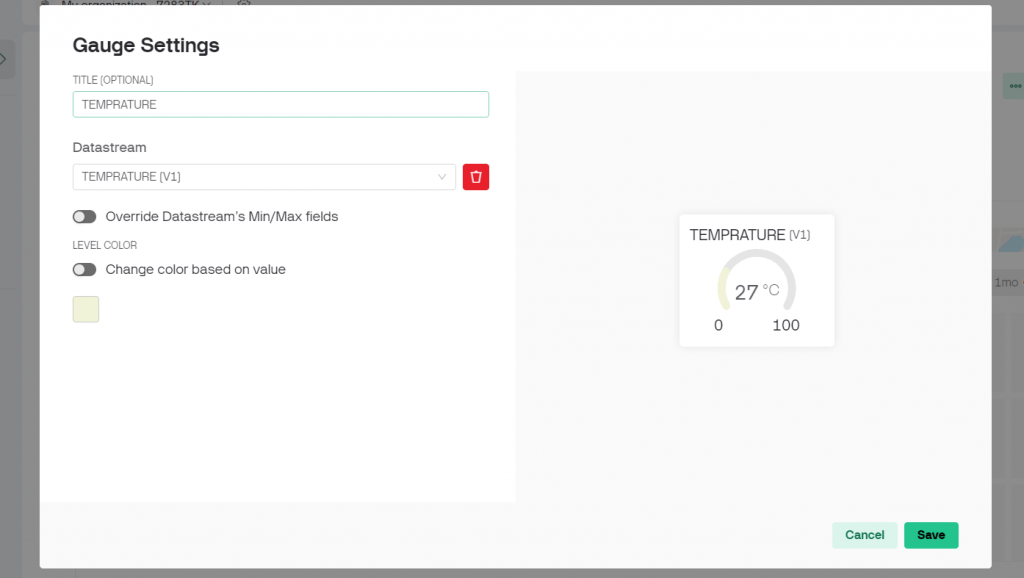
STEP-9: give the title as Temperature
Select the data stream as V1 and click Save
STEP-10: Do this for other two gauge also that is humidity and gas sensor.
Add all the three gauges and click Save
From Blynk console go to Devices and add New Device
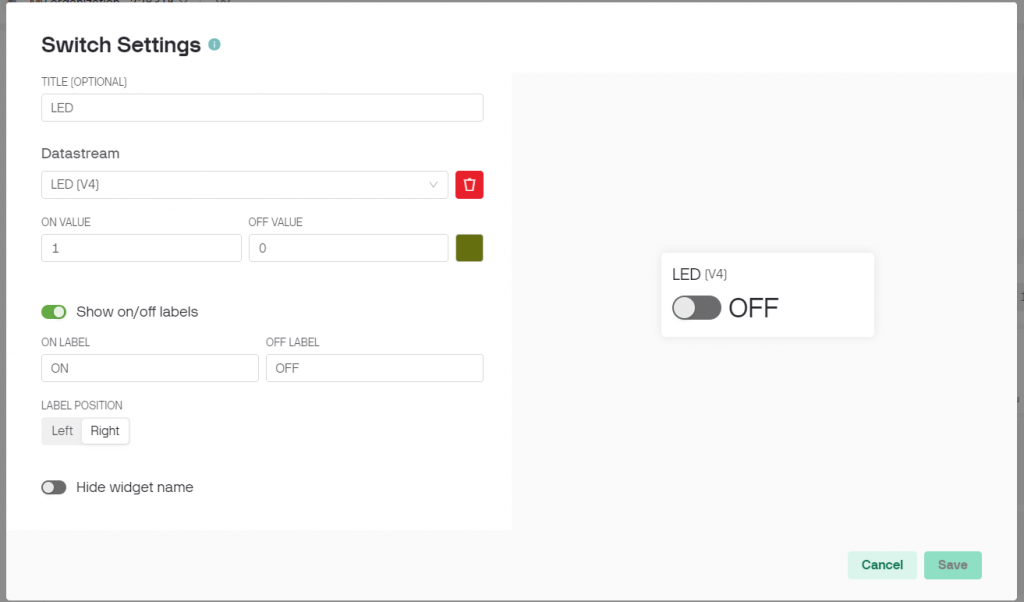
STEP-11: From Web Dashboard Drag and Drop a Switch and go to the settings of the switch.
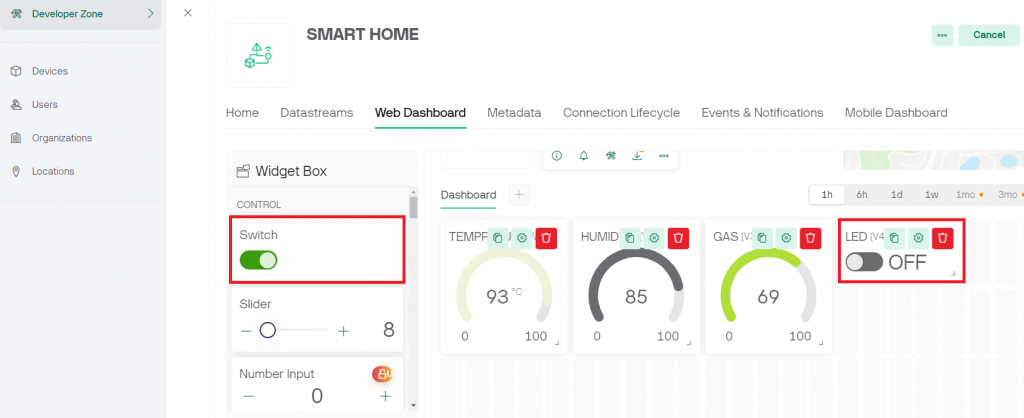
STEP-12: Give TITLE as LED
Choose Datastream as V4
Click Save
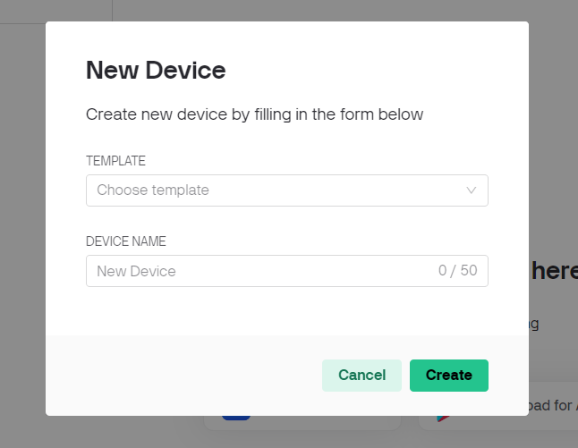
STEP-13: choose the option From Template
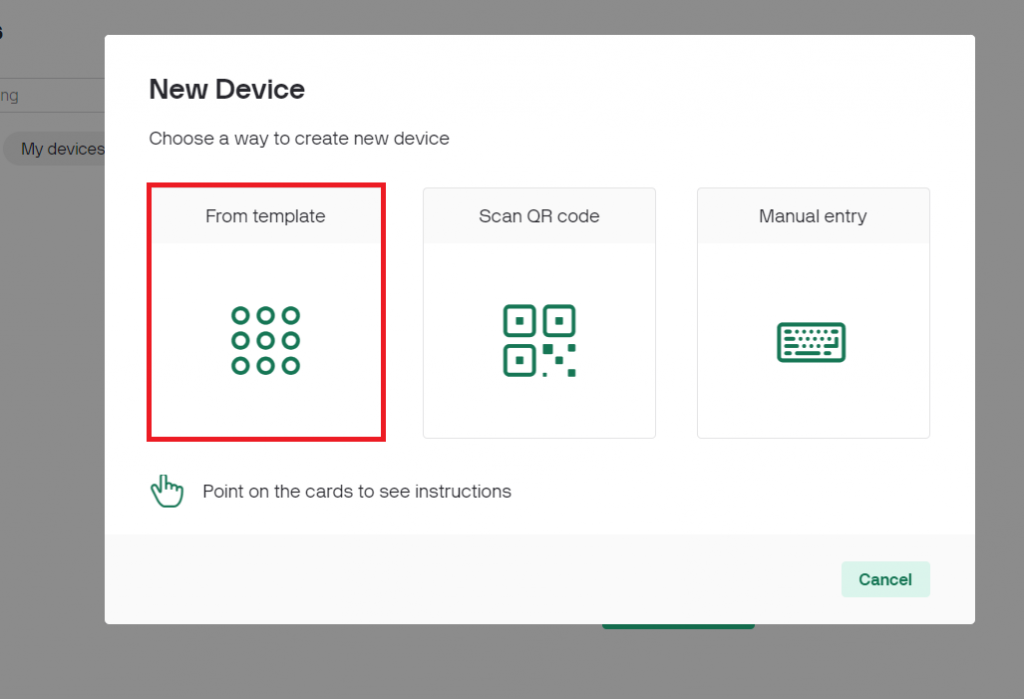
STEP-14: From the option choose template select your project name that is smart home and give a device name
Click on Create
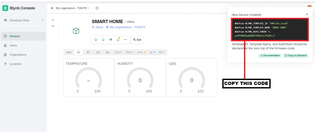
STEP-15: This type of window will open copy the Blynk template name, Blynk template id and authorization token and paste it in the code. you copy that from the black box show on the screen
Step-16: paste the code before the main code
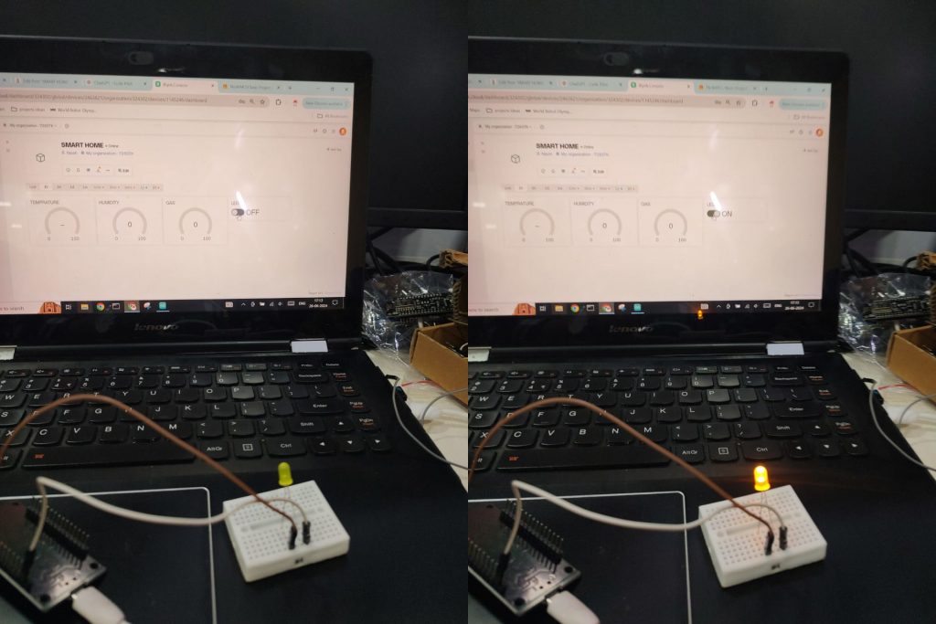
Controlling LED using the Blynk app: