Description:
This project aims to automate the irrigation process on a farm by using a soil moisture sensor, a relay, and an Arduino microcontroller. The system operates based on the soil’s moisture content, ensuring that plants receive water precisely when needed, thus optimizing water usage and promoting healthier crops.
The core component of the system is the soil moisture sensor. This sensor is embedded into the soil, typically at root level, where it continuously measures the moisture level of the soil. The sensor outputs an analog signal that correlates with the soil’s moisture content. A higher analog value indicates wetter soil, while a lower value signifies dry soil.
Connected to the Arduino, the soil moisture sensor sends its readings to the microcontroller. The Arduino processes these readings using a programmed algorithm. The algorithm compares the current moisture reading against a predefined threshold. This threshold determines the point at which the soil is considered dry enough to trigger irrigation.
When the soil moisture level drops below the set threshold, the Arduino activates a relay module. The relay, in turn, controls the water supply system such as a pump or valve. This mechanism allows water to flow into the irrigation system and subsequently into the soil, hydrating the plants.
Once the soil moisture level returns to an acceptable range (above the threshold), the Arduino deactivates the relay, stopping the irrigation process. This automation ensures that the farm receives water only when necessary, preventing over-watering or under-watering of the crops.
Components Needed:
- Arduino Uno X1
- Soil Moisture Sensor X1
- Single Channel Relay Module X1
- Motor Pump Module X1
- Jumper Wires [Male to Female X4 And Some Extra wire]
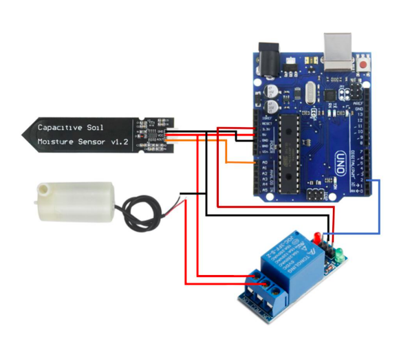
Wiring Connections:
- Connect the Soil Moisture Sensor:
- VCC pin to 5V of Arduino
- GND pin to GND of Arduino
- A0 pin to A0 of Arduino
- Connect the Relay Module:
- VCC to 5V of Arduino
- GND to GND of Arduino
- IN (Signal) to digital pin 2 of Arduino
- Connect the water pump module:
- Positive terminal to COM of Relay
- Negative terminal to GND
// Pin definitions
const int soilMoisturePin = A0;
const int relayControlPin = 2;

// Threshold for soil moisture (adjust as needed)
const int moistureThreshold = 500;

void setup() {
  pinMode(relayControlPin, OUTPUT);
  digitalWrite(relayControlPin, LOW); // Ensure relay is initially off

  Serial.begin(9600);
}

void loop() {
  int moistureValue = analogRead(soilMoisturePin);

  Serial.print("Soil Moisture: ");
  Serial.println(moistureValue);

  if (moistureValue < moistureThreshold) {
    // Turn on the relay (activate the water pump)
    digitalWrite(relayControlPin, HIGH);
    Serial.println("Watering activated");
  } else {
    // Turn off the relay (deactivate the water pump)
    digitalWrite(relayControlPin, LOW);
    Serial.println("Watering deactivated");
  }

  delay(1000); // Delay before next reading
}