Project Description:
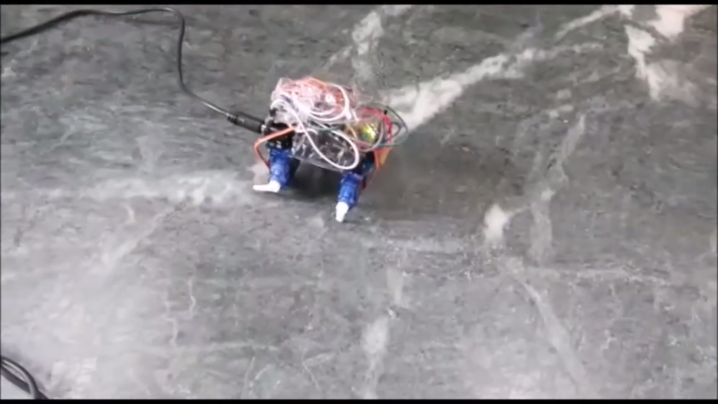
Robotic Insect project involves creating a robotic insect that dances using an Arduino and four servo motors as its legs. The project demonstrates the basic principles of robotics and servo motor control. The robotic insect is designed to perform simple dance movements, providing a fun and engaging way to learn about robotics, coding, and mechanical design. This project is ideal for students interested in robotics and automation. Additionally, this project helps students create their small DIY robots, which they can play with and get entertained by while learning the integration of other components to create new robots based on STEM concepts.
Components Required:
- Arduino Uno with cable x 1
- Micro Servo Motors SG90s x 4
- Jumper Wires – Male to Female x 12
- Breadboard small
Learning Outcomes
- Introduction to Robotics: Understand the basics of robotic movement and control using servos and Arduino.
- Hands-On Engineering: Gain experience in assembling a functional robotic system.
- STEM Integration: Explore the integration of multiple components (sensors, motors, controllers) in a project-based learning environment.
- DIY Robotics: Encourage creativity and problem-solving by allowing students to create their own small DIY robots, combining education and entertainment.
Conclusion:
This project will result in a fun and interactive robotic insect that dances when powered on, providing an excellent introduction to robotics and servo control.
IMAGE:
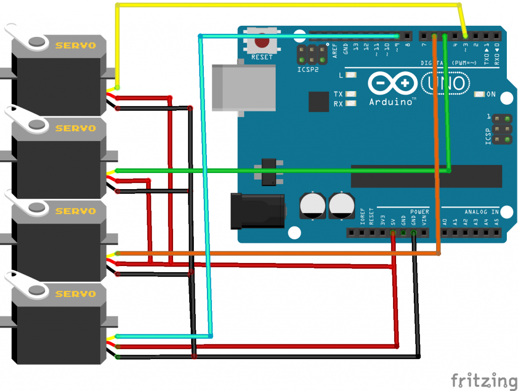
Connections:
- Power Connections:
- Connect the power supply’s positive terminal to the Arduino’s VIN pin and the servo motors’ VCC pins.
- Connect the power supply’s negative terminal to the Arduino’s GND pin and the servo motors’ GND pins.
- Servo Motor
- Servo 1 Signal (Leg 1) to Arduino Digital Pin 3
- Servo 2 Signal (Leg 2) to Arduino Digital Pin 5
- Servo 3 Signal (Leg 3) to Arduino Digital Pin 6
- Servo 4 Signal (Leg 4) to Arduino Digital Pin 9
CIRCUIT DIAGRAM:
CODE:
#include <Servo.h>

Servo servo1; // Create servo objects
Servo servo2;
Servo servo3;
Servo servo4;

void setup() {
  servo1.attach(3);  // Attach servos to pins
  servo2.attach(5);
  servo3.attach(6);
  servo4.attach(9);
}

void loop() {
  // Simple dance moves
  for (int pos = 0; pos <= 180; pos += 10) {
    servo1.write(pos);
    servo2.write(180 - pos);
    servo3.write(pos);
    servo4.write(180 - pos);
    delay(100);
  }
  for (int pos = 180; pos >= 0; pos -= 10) {
    servo1.write(pos);
    servo2.write(180 - pos);
    servo3.write(pos);
    servo4.write(180 - pos);
    delay(100);
  }
  // Add more dance moves as needed
}


