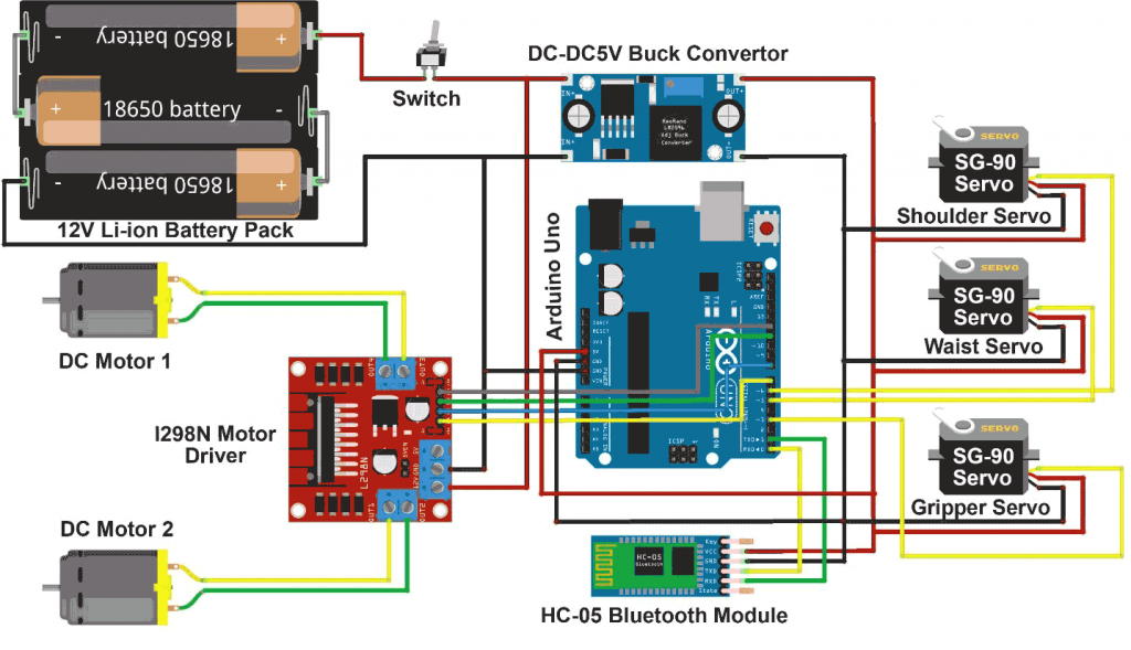
| Introduction :- A pick-and-place robot car is an advanced type of robotic system that combines mobility with the ability to manipulate objects. This project involves a mobile robotic car that can move to a designated location, pick up an object using a robotic arm or gripper, and then transport and place the object at a different location. Here’s an explanation of the project working, including the components involved and how they interact: Working Principle The pick-and-place robot car operates based on the following principles: Mobility: The robot car moves to the target location where the object is to be picked up. This movement is controlled by a set of wheels driven by DC motors. Sensing: Sensors such as ultrasonic sensors are used to detect the presence of obstacles and navigate the robot car to the target location. Object Detection and Positioning: Once at the target location, the robot uses additional sensors or cameras to locate and position itself relative to the object to be picked up. Pick Mechanism: A robotic arm or gripper, controlled by servos or stepper motors, is used to pick up the object. Placement: The robot car then moves to the designated drop-off location, where the robotic arm or gripper places the object. Components Description 1. Arduino Board Description: The central microcontroller that processes sensor data and controls the motors and servos. Function: Manages the overall operation of the robot car, including movement, object detection, and manipulation. 2. DC Motors and Motor Driver (e.g., L298N) Description: DC motors drive the wheels of the robot car, and the motor driver controls the motors. Function: Provide mobility to the robot car. 3. Servo Motors Description: Used to control the movements of the robotic arm or gripper. Function: Allow precise control of the arm for picking and placing objects. 4. Robotic Arm/Gripper Description: The end effector that physically picks up and places objects. Function: Manipulates objects as required by the task. 5. Ultrasonic Sensors (e.g., HC-SR04) Description: Sensors that measure distance to detect obstacles and help navigate the robot car. Function: Provide input to avoid collisions and ensure the robot reaches the correct location. 6. Infrared Sensors or Camera (Optional) Description: Used for more precise object detection and positioning. Function: Assist in accurately locating the object to be picked up. 7. Power Supply (Battery Pack) Description: Provides the necessary voltage and current to power the motors, servos, and Arduino. Function: Ensures the robot car has sufficient power to operate. 8. Chassis Description: The physical frame of the robot car, which holds all the components together. Function: Provides structural support and housing for all components. Project Working Steps Initialization: Power up the system and initialize all components. This includes setting up the Arduino, sensors, motors, and servos. Movement to Target Location: Use ultrasonic sensors to navigate the robot car to the location of the object. The Arduino processes the sensor data to avoid obstacles and guide the car. Object Detection and Positioning: Once at the target location, use additional sensors (like infrared or a camera) to precisely locate the object. Adjust the car’s position if necessary. Pick Operation: Control the robotic arm or gripper using servo motors to pick up the object. This involves precise movements of the arm to grip the object securely. Transport: After picking up the object, navigate the robot car to the drop-off location using the same obstacle avoidance and navigation techniques. Place Operation: Control the robotic arm or gripper to place the object at the designated location. Ensure the object is released securely. Return to Start or Idle State: After placing the object, the robot car can either return to its starting position or enter an idle state awaiting further instructions. |
#include <Servo.h>


Servo motor_1;

Servo motor_2;

Servo motor_3;


//#define enA 9  //Enable1 L298 Pin enA

#define in1 7 //Motor1  L298 Pin in1

#define in2 8 //Motor1  L298 Pin in1

#define in3 12 //Motor2  L298 Pin in1

#define in4 11 //Motor2  L298 Pin in1

//#define enB 9  //Enable2 L298 Pin enB


int servo1 = 90;

int servo2 = 0;

int servo3 = 90;


int bt_data;

int Speed = 130;


void setup(){


Serial.begin(9600); // initialize serial communication at 9600 bits per second:


motor_1.attach(5);   // Waist Servo

motor_2.attach(6);   // Shoulder Servo

motor_3.attach(3);   // Gripper Servo


motor_1.write(servo1);

motor_2.write(servo2);

motor_3.write(servo3);


//pinMode(enA, OUTPUT); // declare as output for L298 Pin enA

pinMode(in1, OUTPUT); // declare as output for L298 Pin in1

pinMode(in2, OUTPUT); // declare as output for L298 Pin in2

pinMode(in3, OUTPUT); // declare as output for L298 Pin in3

pinMode(in4, OUTPUT); // declare as output for L298 Pin in4

//pinMode(enB, OUTPUT); // declare as output for L298 Pin enB


digitalWrite(in1, LOW); //Right Motor forword Pin

digitalWrite(in2, LOW); //Right Motor backword Pin

digitalWrite(in3, LOW); //Left Motor backword Pin

digitalWrite(in4, LOW); //Left Motor forword Pin


delay(1000);

}


void loop(){

//if some date is sent, reads it and saves in state


if(Serial.available() > 0){

bt_data = Serial.read();

Serial.println(bt_data);

if(bt_data > 20)

{Speed = bt_data;}

}


//analogWrite(enA, Speed); // Write The Duty Cycle 0 to 255 Enable Pin A for Motor1 Speed

//analogWrite(enB, Speed); // Write The Duty Cycle 0 to 255 Enable Pin B for Motor2 Speed


if(bt_data == 1)

  {forword(); }  // if the bt_data is '1' the DC motor will go forward

else if(bt_data == 2)

  {backword();}  // if the bt_data is '2' the motor will Reverse

else if(bt_data == 3)

  {turnLeft();}  // if the bt_data is '3' the motor will turn left

else if(bt_data == 4)

  {turnRight();} // if the bt_data is '4' the motor will turn right

else if(bt_data == 5)

  {Stop(); }     // if the bt_data '5' the motor will Stop


else if (bt_data == 8){

if(servo1<180){servo1 = servo1+1;}

motor_1.write(servo1);

}

else if (bt_data == 9){

if(servo1>0){servo1 = servo1-1;}

motor_1.write(servo1);

}


else if (bt_data == 10){

if(servo2>0){servo2 = servo2-1;}

motor_2.write(servo2);

}

else if (bt_data == 11){

if(servo2<180){servo2 = servo2+1;}

motor_2.write(servo2);

}


else if (bt_data == 16){

if(servo3>60){servo3 = servo3-1;}

motor_3.write(servo3);

}

else if (bt_data == 17){

if(servo3<150){servo3 = servo3+1;}

motor_3.write(servo3);

}


delay(30);

}


void forword(){  //forword

digitalWrite(in1, HIGH);   //Right Motor forword Pin

digitalWrite(in2, LOW);   //Right Motor backword Pin

digitalWrite(in3, HIGH);  //Left Motor forward Pin

digitalWrite(in4, LOW);   //Left Motor backward Pin

}


void backword(){ //backword

digitalWrite(in1, LOW);

digitalWrite(in2, HIGH);

digitalWrite(in3, LOW);

digitalWrite(in4, HIGH);

}


void turnRight(){ //turnRight

digitalWrite(in1, LOW);

digitalWrite(in2, HIGH);

digitalWrite(in3, HIGH);

digitalWrite(in4, LOW);

}


void turnLeft(){ //turnLeft

digitalWrite(in1, HIGH);

digitalWrite(in2, LOW);

digitalWrite(in3, LOW);

digitalWrite(in4, HIGH);

}


void Stop(){ //stop

digitalWrite(in1, LOW);

digitalWrite(in2, LOW);

digitalWrite(in3, LOW);

digitalWrite(in4, LOW);

}


