The Overloaded Van Indicator project is designed to address the critical issue of vehicle overloading, which can lead to increased wear and tear, compromised safety, and legal violations. This innovative solution uses an Arduino UNO microcontroller, a force sensor, an I2C LCD screen, an L298N motor driver, and BO motors to create a smart monitoring system.
The force sensor is placed to measure the weight of the load in real-time. The Arduino processes this data and displays the current weight on the LCD screen. If the load exceeds a predefined safe limit, the system triggers an alert and stops the vehicle’s motors to prevent movement. This immediate feedback ensures that the van does not operate under dangerous conditions.
The simplicity and effectiveness of this system make it a practical solution for real-world applications. By providing continuous weight monitoring and automatic overload prevention, it enhances vehicle safety, reduces maintenance costs, and ensures compliance with transportation regulations.
Moreover, the project is easily customizable and scalable. Additional features, such as audible alerts and remote monitoring, can be integrated to enhance its functionality. Overall, the Overloaded Van Indicator project demonstrates how technology can be leveraged to solve everyday problems in a cost-effective and efficient manner.
Components Required:
- Arduino UNO x1
- 5v Buzzer x1
- Force Sensor x1
- I2C LCD x1
- L298N Motor Driver x1
- BO Motor x4
- 18650 Li-ion Battery x1
- 10kohm Resistor x1
- Jumper Wires
Components Description
- Arduino UNO: The microcontroller that reads sensor data and controls the other components.
- Force Sensor: Measures the weight of the load in the van.
- I2C LCD: Displays the weight and alert messages.
- L298N Motor Driver: Controls the motors based on the weight reading.
- BO Motors: Simulates the movement of the van.
- Jumper Wires: Connects all the components.
Step-by-Step Connection
Setup and Connections:
- Connect the force sensor to the analog input pin of the Arduino UNO.
- Connect the I2C LCD to the Arduino UNO using the I2C pins.
- Connect the L298N motor driver to the Arduino and the BO motors. The motor driver will be powered by the 18650 Li-ion Battery.
- Use jumper wires to make all necessary connections between the components.
Force Sensor Calibration:
- Write a code to read the analog values from the force sensor and convert these values into weight measurements.
- Calibrate the force sensor to ensure accurate weight measurements. This might involve taking multiple readings with known weights and mapping the sensor values accordingly.
Display on I2C LCD:
- Write code to initialize the I2C LCD and display messages.
- Display the current weight detected by the force sensor on the LCD.
- Set a threshold value for the maximum permissible load. If the weight exceeds this value, display an “Overloaded” message on the LCD.
Motor Control with L298N:
- Write code to control the BO motors using the L298N motor driver.
- Define actions based on the load detected. For example, if the van is overloaded, the motors could be used to lock the van’s doors or trigger an alarm.
Integration and Testing:
- Combine all the individual pieces of code and test the complete system.
- Place weights on the force sensor to simulate loading the van and observe the behavior on the LCD.
- Ensure that the motors respond correctly based on the load status.
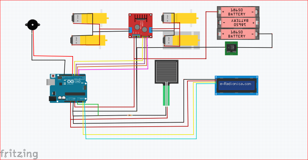
Circuit Connections:
Force Sensor Connections:
- Negative Terminal: Connect the negative terminal of the Force Sensor to Arduino A0 (analog input).
- Positive Terminal: Connect the positive terminal of the Force Sensor to 5V VCC from the Arduino.
- Grounding with Resistor: Connect a 10kΩ resistor between the negative terminal of the Force Sensor and GND (ground) of the Arduino. This forms a voltage divider circuit.
L298N Motor Driver Connections:
- Motor Power Supply: Connect an appropriate external power supply (typically 6V to 12V DC) to the L298N motor driver module.
- Motor Control Pins: Connect the DC motors to the following pins on the L298N motor driver module:
- Pin 4 (IN1): Connect to one terminal of Motor 1.
- Pin 5 (IN2): Connect to the other terminal of Motor 1.
- Pin 6 (IN3): Connect to one terminal of Motor 2.
- Pin 7 (IN4): Connect to the other terminal of Motor 2.
Buzzer Connections:
- Connect positive pin of the Buzzer to digital pin 8 of Arduino Uno and Negative to GND pin of Arduino.
Arduino Connections:
- Ground (GND): Connect Arduino GND to the ground (GND) rail of the breadboard and to the L298N motor driver ground.
- 5V VCC: Connect Arduino 5V to the VCC rail of the breadboard for powering the Force Sensor and other components requiring 5V.
- Analog Input (A0): Connect Arduino A0 to the negative terminal of the Force Sensor for reading analog sensor data via 10kohm resistor.
- Control Pins to L298N: Connect Arduino digital pins (e.g., 4, 5, 6, 7) to the corresponding control pins on the L298N motor driver module (IN1, IN2, IN3, IN4).
Applications:
Automatic Elevator (Lift) Control System: Controls the operation of the elevator, manages floor selection. Used to detect the weight of passengers or objects inside the elevator to ensure it doesn’t exceed its maximum capacity.
Construction Equipment and Vehicles: Implemented in trucks or vehicles used in construction sites to monitor the weight of construction materials like gravel, sand, or concrete.
Refrigerated Delivery Vehicles: Installed in refrigerated trucks or vans used for food delivery to monitor and maintain load limits, ensuring proper refrigeration and transport conditions.
//STEMROBO TECHNOLOGIES PRIVATE LIMITED
//TANYA GUPTA INNOVATION ENGINEER
#include <Wire.h>
#include <LiquidCrystal_I2C.h>

#define FORCE_SENSOR_PIN A0
#define MOTOR_PIN1 4  // Connect to IN1 on L298N for Motor 1
#define MOTOR_PIN2 5  // Connect to IN2 on L298N for Motor 1
#define MOTOR_PIN3 6  // Connect to IN3 on L298N for Motor 2
#define MOTOR_PIN4 7  // Connect to IN4 on L298N for Motor 2
#define BUZZER_PIN 8   // Buzzer pin
#define OVERLOAD_THRESHOLD 1000

LiquidCrystal_I2C lcd(0x27, 16, 2);

void setup() {
  pinMode(FORCE_SENSOR_PIN, INPUT);
  pinMode(MOTOR_PIN1, OUTPUT);
  pinMode(MOTOR_PIN2, OUTPUT);
  pinMode(MOTOR_PIN3, OUTPUT);
  pinMode(MOTOR_PIN4, OUTPUT);
  pinMode(BUZZER_PIN, OUTPUT); // Set buzzer pin as output
  lcd.begin();
  lcd.backlight();
  lcd.print("Weight: ");
}

void loop() {
  int sensorValue = analogRead(FORCE_SENSOR_PIN);
  float weight = map(sensorValue, 0, 1023, 0, 2000); // Adjust mapping as needed

  lcd.setCursor(0, 1);
  lcd.print(weight);
  lcd.print(" g");

  if(weight > OVERLOAD_THRESHOLD) {
    lcd.setCursor(0, 0);
    lcd.print("Overloaded");
    // Stop both motors if overloaded
    digitalWrite(MOTOR_PIN1, LOW);
    digitalWrite(MOTOR_PIN2, LOW);
    digitalWrite(MOTOR_PIN3, LOW);
    digitalWrite(MOTOR_PIN4, LOW);
    // Activate buzzer
    digitalWrite(BUZZER_PIN, HIGH);
  } else {
    lcd.setCursor(0, 0);
    lcd.print("Load OK     ");
    // Run both motors if not overloaded
    digitalWrite(MOTOR_PIN1, HIGH);
    digitalWrite(MOTOR_PIN2, LOW);
    digitalWrite(MOTOR_PIN3, HIGH);
    digitalWrite(MOTOR_PIN4, LOW);
    // Deactivate buzzer
    digitalWrite(BUZZER_PIN, LOW);
  }

  delay(500);
}


