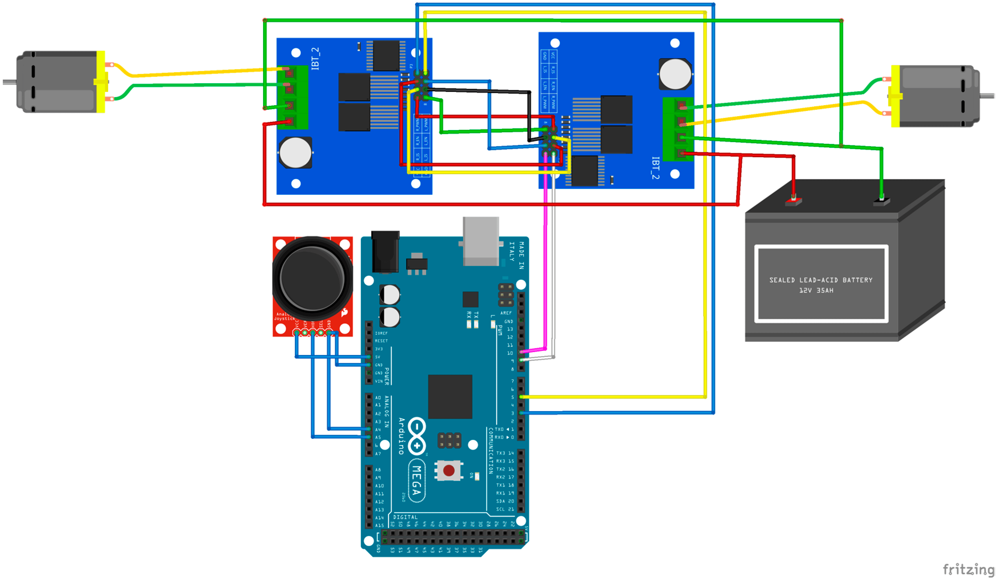
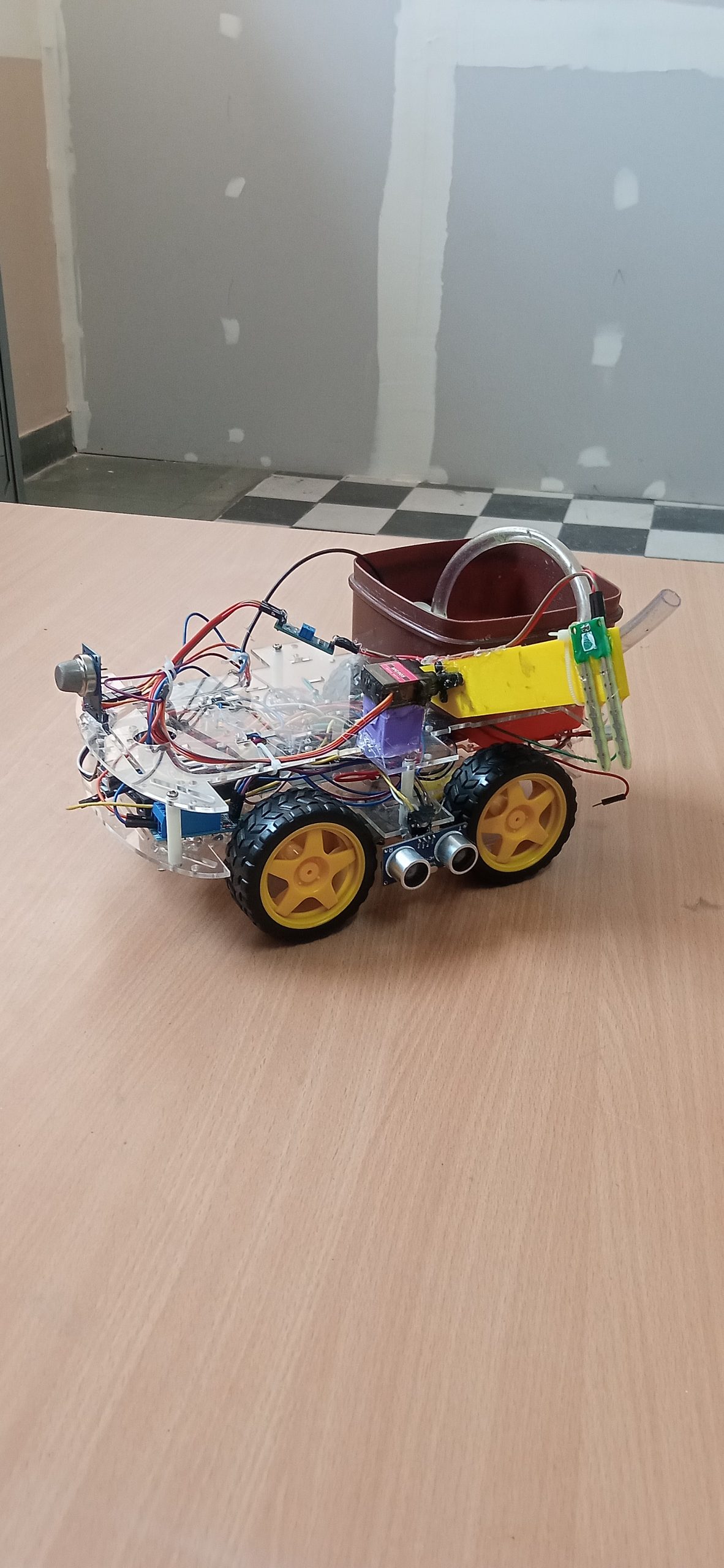
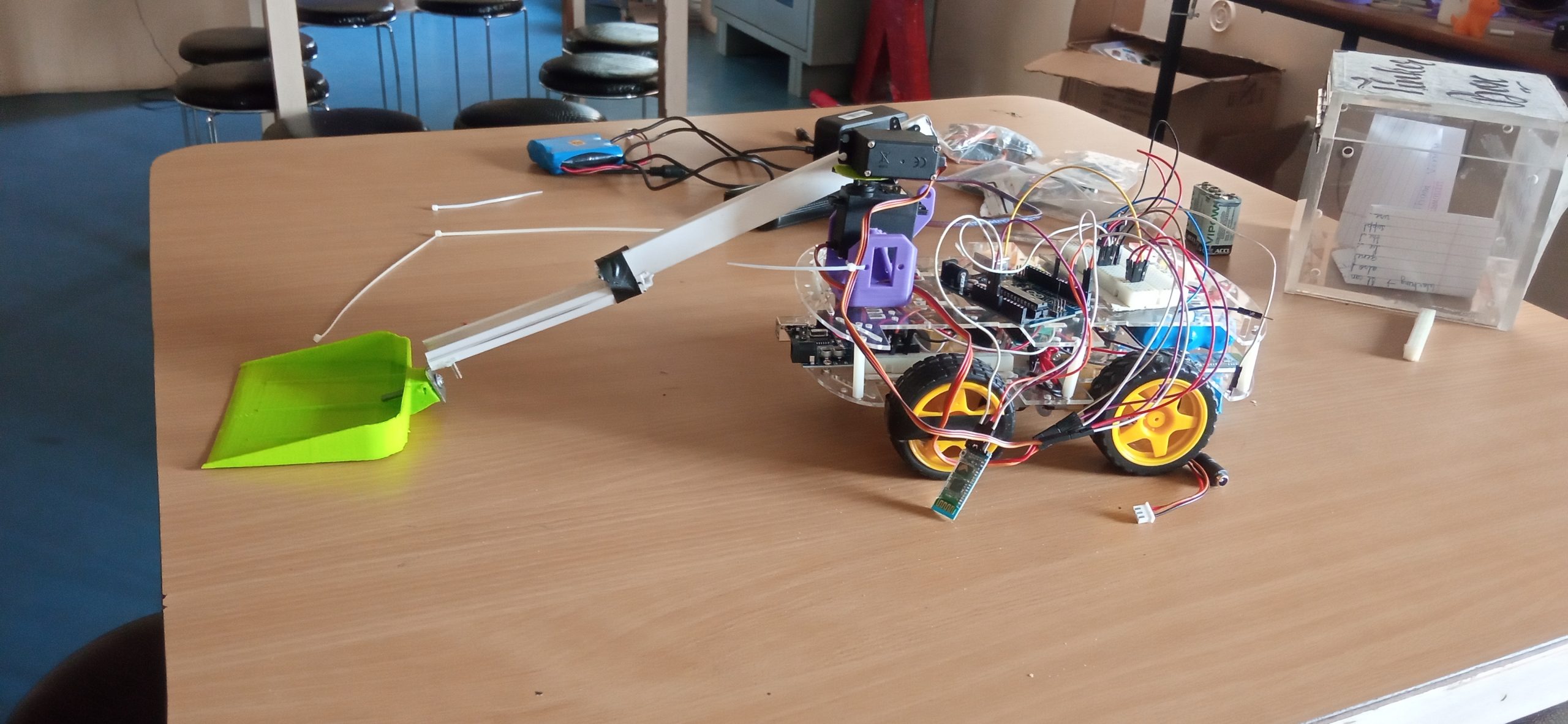
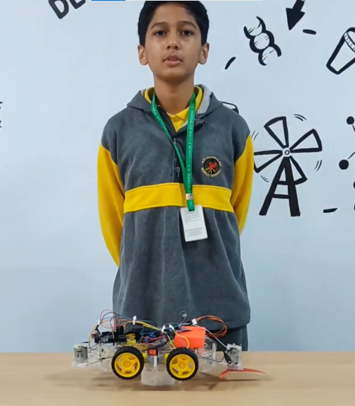
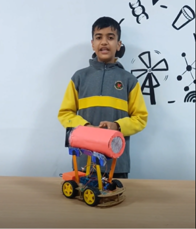
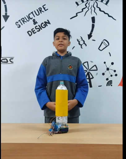
| The Medical Assistant Bot is an innovative robotic solution that combines Arduino technology with healthcare assistance, designed to improve efficiency in hospitals and medical facilities. This small, autonomous vehicle is equipped with a variety of components to navigate corridors, deliver medications, and assist healthcare professionals with routine tasks such as sample retrieval. Components: Arduino Uno: The brain of the robot, responsible for controlling all the actions and behaviors. HC-05 Bluetooth Module: Facilitates wireless communication between the bot and a smartphone or tablet, allowing healthcare staff to control or monitor the bot remotely. Bo-motors: Drive the wheels of the bot, enabling smooth and reliable movement through hospital corridors. Motor Driver Shield: Controls the Bo-motors by regulating the power and direction of the wheels for precise navigation. Ultrasonic Sensors: (Optional) These sensors can be added to detect obstacles and ensure safe movement in crowded hospital environments. Power Supply: A battery pack powers the Arduino and motors for uninterrupted operation. Working: The Arduino Uno processes commands sent from a paired device via the HC-05 Bluetooth module. Through an app, medical staff can control the bot or program it for semi-autonomous tasks like navigating predefined routes. The Motor Driver Shield regulates the power supply to the Bo-motors, enabling the bot to move forward, backward, or turn, as needed. Sensors can be added to detect obstacles and avoid collisions during navigation. The bot is designed to deliver medications or transport samples autonomously, enhancing efficiency, reducing manual labor, and allowing healthcare staff to focus on patient care. |
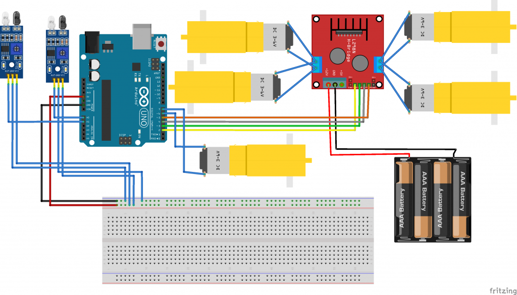
#define in1 2//Motor1  L293 Pin in1

#define in2 3 //Motor1  L293 Pin in1

#define in3 4//Motor2  L293 Pin in1

#define in4 5 //Motor2  L293 Pin in1


#define R_S 6//ir sensor Right

#define L_S 7 //ir sensor Left

void setup(){
  Serial.begin(9600);

pinMode(R_S, INPUT);

pinMode(L_S, INPUT);


pinMode(in1, OUTPUT);

pinMode(in2, OUTPUT);

pinMode(in3, OUTPUT);

pinMode(in4, OUTPUT);


}

void loop(){
Serial.println(R_S);
Serial.println(L_S);
if((digitalRead(R_S) == 1)&&(digitalRead(L_S) == 1))
{forward();}   //if Right Sensor and Left Sensor are at White color then it will call forword function

if((digitalRead(R_S) == 0)&&(digitalRead(L_S) == 1))
{turnRight();} //if Right Sensor is Black and Left Sensor is White then it will call turn Right function

if((digitalRead(R_S) == 1)&&(digitalRead(L_S) == 0))
{turnLeft();}  //if Right Sensor is White and Left Sensor is Black then it will call turn Left function

if((digitalRead(R_S) == 0)&&(digitalRead(L_S) == 0))
{Stop();} //if Right Sensor and Left Sensor are at Black color then it will call Stop function

}

void forward(){  //forword

digitalWrite(in1, HIGH); //Right Motor forword Pin

digitalWrite(in2, LOW);  //Right Motor backword Pin

digitalWrite(in3, LOW);  //Left Motor backword Pin

digitalWrite(in4, HIGH); //Left Motor forword Pin

}

void turnRight(){ //turnRight

digitalWrite(in1, LOW);  //Right Motor forword Pin

digitalWrite(in2, HIGH); //Right Motor backword Pin

digitalWrite(in3, LOW);  //Left Motor backword Pin

 digitalWrite(in4, HIGH); //Left Motor forword Pin

}

void turnLeft(){ //turnLeft

digitalWrite(in1, HIGH); //Right Motor forword Pin

digitalWrite(in2, LOW);  //Right Motor backword Pin

digitalWrite(in3, HIGH); //Left Motor backword Pin

digitalWrite(in4, LOW);  //Left Motor forword Pin

}

void Stop(){ //stop

digitalWrite(in1, LOW); //Right Motor forword Pin

digitalWrite(in2, LOW); //Right Motor backword Pin

digitalWrite(in3, LOW); //Left Motor backword Pin

digitalWrite(in4, LOW); //Left Motor forword Pin

}

