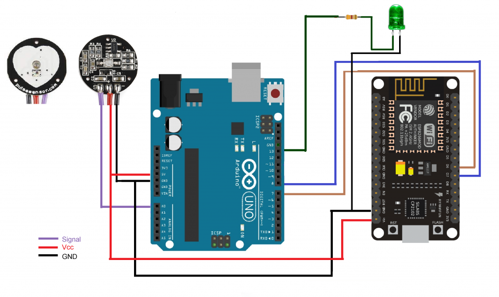
| IoT-based health and pulse rate monitoring system using ESP8266 and a heart rate sensor: Components: 1. ESP8266: This is a low-cost Wi-Fi microcontroller that allows you to connect your project to the internet. It can be programmed like any other microcontroller and is particularly useful for IoT projects due to its built-in Wi-Fi capabilities. 2. Heart Rate Sensor: This sensor typically includes an infrared LED and a photodetector to measure the user’s heart rate by detecting changes in blood volume in the fingertip. It outputs analog or digital data that can be processed by the ESP8266. Operation: 3. Data Acquisition: The heart rate sensor is attached to the user’s fingertip. It continuously measures the user’s heart rate and provides analog or digital data representing the pulse rate. 4. ESP8266 Integration: The ESP8266 reads the data from the heart rate sensor. It then processes this data and prepares it for transmission over Wi-Fi. 5. Wi-Fi Connectivity: The ESP8266 connects to a Wi-Fi network, either a local network or the internet, allowing it to transmit data to a remote server or cloud platform. 6. Data Transmission: The ESP8266 sends the heart rate data to a remote server or cloud platform using HTTP, MQTT, or other communication protocols. This data can be sent periodically or in real-time, depending on the application requirements. 7. Cloud Platform: The heart rate data is received by a cloud platform or server. This platform can store data, perform analysis on it, and provide a user interface for visualization and monitoring. 8. User Interface: Users can access the heart rate data through a web-based dashboard, mobile app, or other user interface provided by the cloud platform. They can monitor their heart rate in real-time and view historical data to track trends over time. Features and Benefits: · Real-time Monitoring: Users can monitor their heart rate in real-time from anywhere with an internet connection. · Remote Accessibility: The system allows healthcare professionals or caregivers to remotely monitor the user’s heart rate and health status. · Data Analysis: The cloud platform can perform analysis on the heart rate data, such as detecting irregularities or trends, and provide insights or alerts accordingly. · Historical Tracking: Users can track their heart rate trends over time, allowing them to identify patterns or changes in their health. This IoT-based health and pulse rate monitoring system provides a convenient and accessible way for users to monitor their heart rate and track their health status using ESP8266 and a heart rate sensor. |
#include <SoftwareSerial.h>
SoftwareSerial SMESerial (D6, D7);
// Fill-in information from your Blynk Template here

#define BLYNK_TEMPLATE_ID "___"
#define BLYNK_DEVICE_NAME "____"
#define BLYNK_AUTH_TOKEN "_____"

#define BLYNK_PRINT Serial

#include <ESP8266WiFi.h>
#include <BlynkSimpleEsp8266.h>

char auth[] = BLYNK_AUTH_TOKEN;
char ssid[] = "*****";
char pass[] = "*****";

BlynkTimer timer;
void setup()
{
   Blynk.begin(auth, ssid, pass);
  Serial.begin(9600);
  SMESerial.begin(9600);
  delay(100);

timer.setInterval(1000L, sensor); }

void loop() {
   Blynk.run();
  timer.run();
}

void sensor()
{
  if (SMESerial.available()<1)  return;
  char R=SMESerial.read();
  if (R!='\r')                 return;
  int bpm=SMESerial.parseInt();
  Serial.println("♥  A HeartBeat Happened ! ");
  Serial.println(String("BPM: ") + bpm);
  Blynk.virtualWrite(V0, bpm);
}
#include <SoftwareSerial.h>
SoftwareSerial SMESerial (6, 7);
#define USE_ARDUINO_INTERRUPTS true
#include <PulseSensorPlayground.h>

const int PulseWire = A0;
const int Ind = 13;
int Threshold = 550;

PulseSensorPlayground pulseSensor;

void setup() {
  Serial.begin(9600);
  SMESerial.begin(9600);
  Serial.println("Serial Begin");

  // Configure the PulseSensor object, by assigning our variables to it.
  pulseSensor.analogInput(PulseWire);
  pulseSensor.blinkOnPulse(Ind);
  pulseSensor.setThreshold(Threshold);
  delay(2000);

   if (pulseSensor.begin()) { // If puslse sensor connect properly
    Serial.println("We created a pulseSensor Object !");
  }
}

void loop() {

 int myBPM = pulseSensor.getBeatsPerMinute();
if (pulseSensor.sawStartOfBeat()) {            // Constantly test to see if "a beat happened".

   Serial.println("♥  A HeartBeat Happened ! ");
   Serial.println(String("BPM: ") + myBPM);

   SMESerial.print('\r');
   SMESerial.print(myBPM);
   SMESerial.print('|');
   SMESerial.print('\n');

   Serial.print('\r');
   Serial.print(myBPM);
   Serial.print('|');
   Serial.print('\n');
}
  delay(1000);
}


