A human brain simulator prototype using Arduino Uno, ultrasonic sensor, microphone sensor, DHT11 temperature and humidity sensor, and LEDs can serve as an educational tool or a research platform to understand basic brain functions and responses to various stimuli. Here’s a detailed description of such a system:
Components:
1. Arduino Uno: The main controller unit responsible for processing sensory inputs, generating responses, and controlling the output devices such as LEDs.
2. Ultrasonic Sensor: Used to simulate proximity detection or depth perception. It emits ultrasonic waves and measures the time taken for the waves to bounce back from nearby objects, providing distance information to the Arduino Uno.
3. Microphone Sensor: Detects sound waves and converts them into electrical signals. It enables the simulation of auditory perception by capturing sound inputs from the environment and transmitting them to the Arduino Uno for processing.
4. DHT11 Temperature and Humidity Sensor: Measures ambient temperature and humidity levels. It adds another sensory dimension to the simulation, allowing the Arduino Uno to respond to changes in environmental conditions.
5. LEDs: Light Emitting Diodes serve as output indicators to mimic neural activity or physiological responses. They can be programmed to light up in different patterns or colors to represent various states or reactions.
Operation:
6. Sensory Input Processing: The Arduino Uno continuously monitors inputs from the ultrasonic sensor, microphone sensor, and DHT11 sensor. It processes the data received from these sensors to simulate sensory perception, including vision (proximity detection), hearing (sound detection), and environmental awareness (temperature and humidity sensing).
7. Response Generation: Based on the sensory inputs, the Arduino Uno generates appropriate responses or reactions. These responses can range from simple actions such as illuminating LEDs to complex behaviors simulating decision-making processes.
8. LED Output: The Arduino Uno controls the LEDs to visually represent the simulated brain activity or responses. For example, LEDs may light up in different patterns or sequences to simulate neural firing, cognitive processing, or physiological reactions.
9. Feedback Loop: The system can incorporate feedback mechanisms to adjust its responses based on previous experiences or environmental changes. This allows for adaptive behavior and more realistic simulations of human brain functions.
Benefits:
10. Educational Tool: The human brain simulator provides a hands-on platform for students or researchers to explore basic neuroscience concepts and understand how sensory inputs are processed and integrated to generate responses.
11. Interdisciplinary Learning: Integrating multiple sensors and output devices allows for a multidisciplinary approach to learning, incorporating elements of electronics, programming, biology, and psychology.
12. Customization and Experimentation: The modular design of the simulator allows for easy customization and experimentation. Users can modify sensor inputs, response algorithms, and LED outputs to create unique simulations or study specific phenomena.
13. Engagement and Interaction: The interactive nature of the simulator fosters engagement and interaction, making learning about the brain more immersive and enjoyable.
Overall, a human brain simulator prototype using Arduino Uno, ultrasonic sensor, microphone sensor, DHT11, and LEDs offers a versatile and interactive platform for exploring the complexities of the human brain and its responses to stimuli.
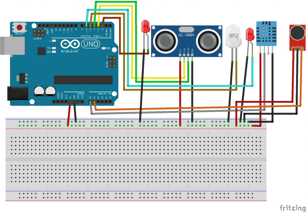
CIRCUIT DIAGRAM
CODE
#include <DHT.h>
#include <NewPing.h>

#define DHTPIN A0          // Pin where the DHT sensor is connected
#define DHTTYPE DHT11     // Type of DHT sensor (DHT11 or DHT22)
#define TRIGGER_PIN 3     // Pin connected to the ultrasonic sensor's trigger
#define ECHO_PIN 4        // Pin connected to the ultrasonic sensor's echo
#define MIC_PIN A1        // Pin connected to the microphone sensor

#define LED_DHT_PIN 2    // Pin connected to the DHT sensor LED
#define LED_ULTRASONIC_PIN 5  // Pin connected to the ultrasonic sensor LED
#define LED_MIC_PIN 6    // Pin connected to the microphone sensor LED

DHT dht(DHTPIN, DHTTYPE);
NewPing sonar(TRIGGER_PIN, ECHO_PIN);
int micValue = 0;

void setup() {
  Serial.begin(9600);
  pinMode(LED_DHT_PIN, OUTPUT);
  pinMode(LED_ULTRASONIC_PIN, OUTPUT);
  pinMode(LED_MIC_PIN, OUTPUT);
  dht.begin();
}

void loop() {
  // Read temperature and humidity from DHT sensor
  float temperature = dht.readTemperature();
  float humidity = dht.readHumidity();

  // Read distance from ultrasonic sensor
  int distance = sonar.ping_cm();

  // Read value from microphone sensor
  micValue = analogRead(MIC_PIN);

  // Print sensor data to serial monitor
  Serial.print("Temperature: ");
  Serial.print(temperature);
  Serial.print("°C, Humidity: ");
  Serial.print(humidity);
  Serial.print("%, Distance: ");
  Serial.print(distance);
  Serial.print("cm, Mic Value: ");
  Serial.println(micValue);

  // Control LEDs based on sensor data
  if (temperature > 25 || humidity > 70) {
    digitalWrite(LED_DHT_PIN, HIGH); // Turn on DHT LED
  } else {
    digitalWrite(LED_DHT_PIN, LOW); // Turn off DHT LED
  }

  if (distance < 10) {
    digitalWrite(LED_ULTRASONIC_PIN, HIGH); // Turn on ultrasonic LED
  } else {
    digitalWrite(LED_ULTRASONIC_PIN, LOW); // Turn off ultrasonic LED
  }

  if (micValue > 500) {
    digitalWrite(LED_MIC_PIN, HIGH); // Turn on microphone LED
  } else {
    digitalWrite(LED_MIC_PIN, LOW); // Turn off microphone LED
  }

  delay(1000); // Delay for 1 second before next iteration
}/ put your main code here, to run repeatedly:

}


