Description:
The IoT-based health monitoring system Project leverages an ESP32 microcontroller and a pulse rate sensor to provide real-time health monitoring capabilities. The system is designed to continuously measure and monitor the pulse rate and send the data to an IoT platform for remote access and analysis. Health Monitoring System Project Using IoT.
Components:
- ESP32 Development Board
- Pulse Rate Sensor (e.g., Pulse Sensor Amped)
- IoT Platform (e.g., ThingSpeak, Blynk, or a custom server)
- Jumper wires
- Breadboard (optional)
- Power supply (e.g., USB cable)
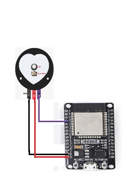
Connection Details:
Pulse Rate Sensor:
- Signal Pin (S):
- Connect to Analog Pin 34 (ADC1_6) on the ESP32.
- VCC (Voltage):
- Connect to 3.3V pin on the ESP32.
- GND (Ground):
- Connect to GND on the ESP32.
// Install WebServer library from Library manager.
#include <WiFi.h>
#include <WebServer.h>
#define pulse 34 // Pin where the pulse sensor is connected (analog pin)
// Network credentials
const char* ssid = “your_SSID”;
const char* password = “your_PASSWORD”;
WebServer server(80);
void handleRoot() {
// Reading sensors
int pulse_value = analogRead(pulse);
pulse_value = map(sensorValue1, 0, 1023, 40, 200);
String html = “<html><head><title>Pulse Sensor Dashboard</title>”;
html += “<style>”;
html += “body { font-family: Arial, sans-serif; text-align: center; background-color: #f4f4f4; }”;
html += “h1 { color: #333; }”;
html += “.sensor { margin: 20px 0; }”;
html += “p { font-size: 1.2em; }”;
html += “.control-buttons a { display: inline-block; margin: 10px; padding: 10px 20px; text-decoration: none; color: white; background-color: #4CAF50; border-radius: 5px; }”;
html += “</style></head><body>”;
html += “<h1>Pulse Sensor Dashboard</h1>”;
html += “<div class=\”sensor\”><p>Gas Level: ” + String(Pulse_value) + “</p></div>”;
html += “</body></html>”;
server.send(200, “text/html”, html);
}
void setup() {
Serial.begin(115200);
pinMode(pulse, INPUT);
// Connect to Wi-Fi
WiFi.begin(ssid, password);
while (WiFi.status() != WL_CONNECTED) {
delay(1000);
Serial.println(“Connecting to WiFi…”);
}
Serial.println(“Connected to WiFi”);
// Start the server
server.on(“/”, handleRoot);
server.begin();
Serial.println(“HTTP server started”);
}
void loop() {
server.handleClient();
}