Project Description:
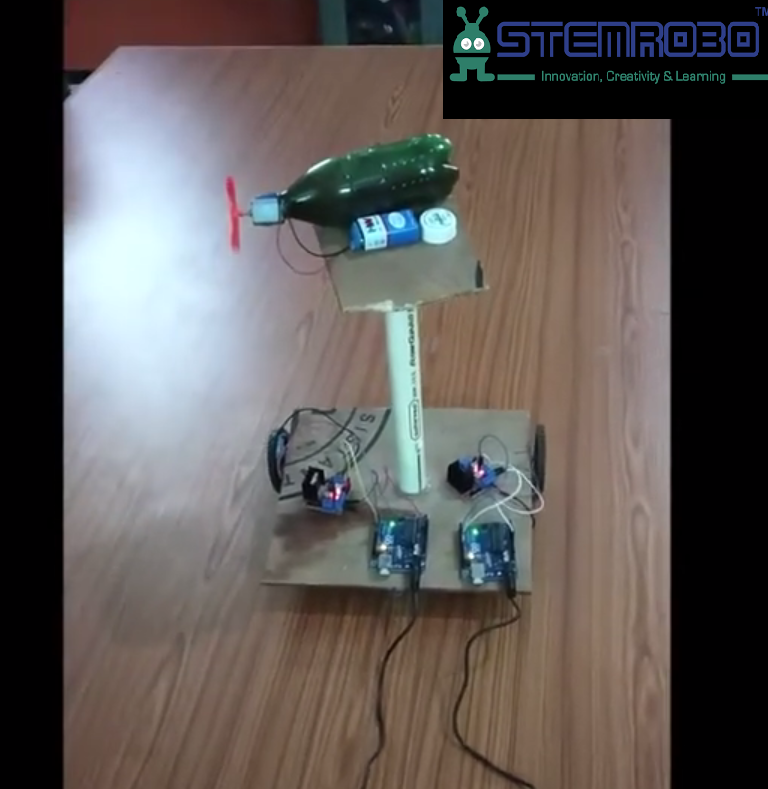
The Farmer Welfare Robot is an innovative solution designed to help farmers safely and efficiently spray pesticides in their fields. This autonomous robot aims to protect farmers from direct exposure to harmful chemicals, which can cause skin-related allergies and other health issues. The robot leverages the Arduino platform to navigate the fields and uniformly spray pesticides, ensuring both the health of the crops and the farmers.
Components Required:
- Arduino uno with cable x 1
- Motor Driver L298N x 1
- DC Motor x 3
- Jumper wires – Male to Female x 12
Male to Male x 2 - 3.7v battery Li-ion 18650 x 3
- Lithium_ion Battery Holder x 1
Conclusion:
The Farmer Welfare Robot provides a practical and efficient solution for pesticide spraying, safeguarding farmers’ health and making field operations easy. This project uses basic electronic components and programming to deliver a valuable tool for modern agriculture. It also safeguards farmers from skin allergies that are caused by the pesticides.
IMAGE:
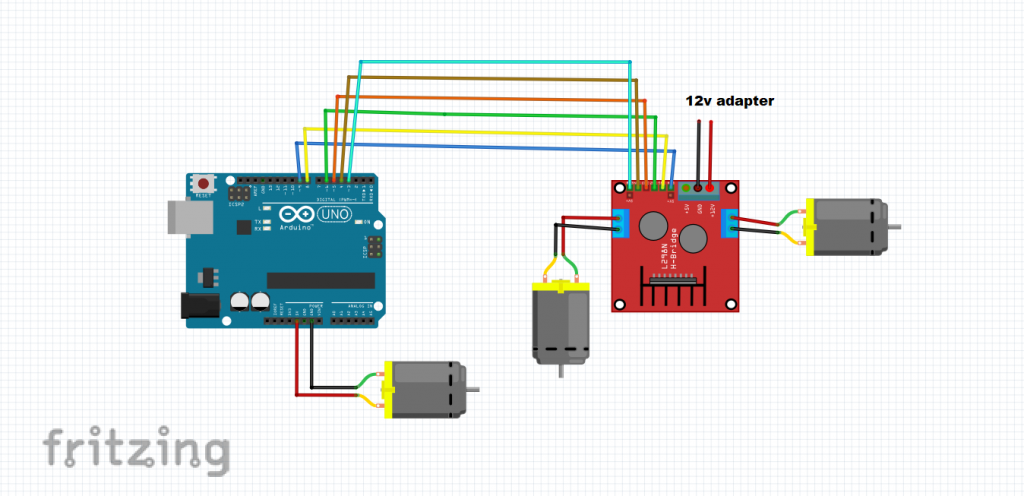
CIRCUIT DIAGRAM:
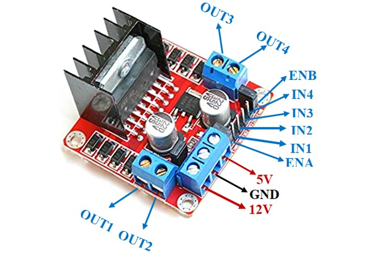
Images of Motor Driver L298N:
Connections:
Connection of Arduino with Motor driver L298N:
- Arduino pin 9 to motor driver pin ENA
- Arduino pin 8 to motor driver pin IN1
- Arduino pin 6 to motor driver pin IN2
- Arduino pin 5 to motor driver pin IN3
- Arduino pin 4 to motor driver pin IN4
- Arduino pin 3 to motor driver pin ENB
Connection of Motor Driver to DC Motors:
- Motor driver L298N pin OUT1 to first DC motor pin 1
- Motor driver L298N pin OUT2 to first DC motor pin 2
- Motor driver L298N pin OUT3 to second DC motor pin 1
- Motor driver L298N pin OUT4 to second DC motor pin 2
- Connect the +12v pin to positive of 12v battery
- Connect the GND pin to negative of 12v battery
Connection of Arduino with third DC Motor:
- Arduino pin 5v to motor pin 1
- Arduino pin GND to motor pin 2
CODE:
int enA = 9;
int in1 = 8;
int in2 = 6;
int enB = 3;
int in3 = 5;
int in4 = 4;

void setup() {

  pinMode(enA, OUTPUT);
  pinMode(enB, OUTPUT);
  pinMode(in1, OUTPUT);
  pinMode(in2, OUTPUT);
  pinMode(in3, OUTPUT);
  pinMode(in4, OUTPUT);


  digitalWrite(in1, LOW);
  digitalWrite(in2, LOW);
  digitalWrite(in3, LOW);
  digitalWrite(in4, LOW);


  analogWrite(enA, 255);
  analogWrite(enB, 255);
}

void loop() {
  moveForward();
}


void moveForward() {

  digitalWrite(in1, HIGH);
  digitalWrite(in2, LOW);


  digitalWrite(in3, HIGH);
  digitalWrite(in4, LOW);
}


