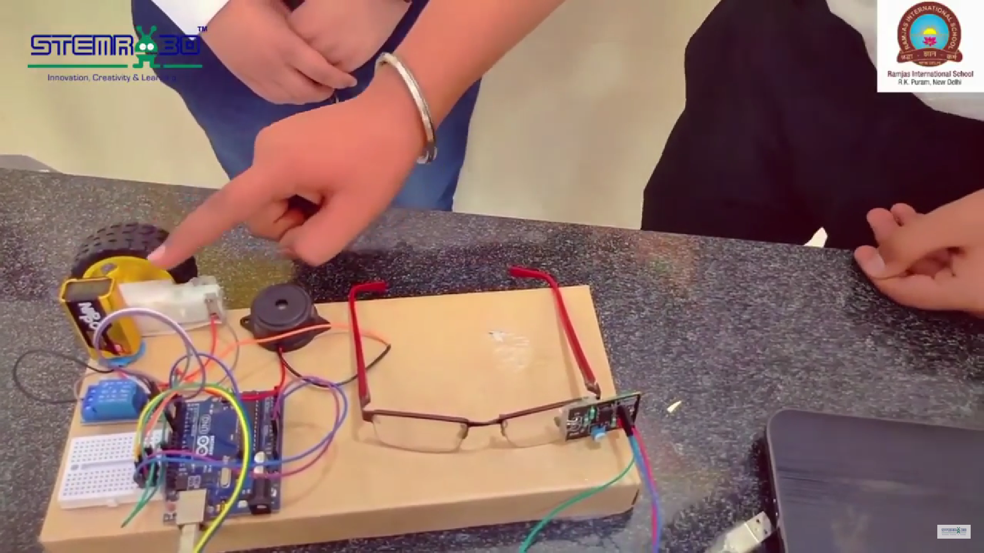
Drwiser Version smart device is designed to be controlled by the learner’s eye movements. It uses an IR sensor, relay, Arduino Uno, and a BO motor to activate a wheel when you open your eye and stop it when you close your eye.
COMPONENTS REQUIRED
- IR SENSOR x1
- Arduino UNO with cable x1
- Single channel Relay module x1
- BO Motor x1
- Wheel x1
- Jumper Wires – male to male x 23
– male to female x 12
Components review:
- IR Sensor:
- The Infrared ray sensor is an electronic device that detects the difference in the amount of light reflected from the object. When your eye is open, the sensor picks up more light and when it’s closed, it picks up less.
- Arduino Uno:
- The Arduino Uno acts as the brain module of the device. It reads the signals received from the IR sensor and decides whether to turn the wheel on or off. It’s like a small computer that can be programmed to operate a specific task.
- Relay:
- The relay works like a switch that the controlled by an Arduino. When the Arduino gets a signal from the IR sensor that your eye is open, it tells the relay to turn on the BO motor and when your eye is closed, the relay turns off the motor.
- BO Motor and Wheel:
- The BO motor is connected to a wheel. When the relay turns the motor on, the wheel starts spinning. When the motor is turned off, the wheel stops.
- Buzzer: A Buzzer is an output device that emits sound in the form of a beep. It is used for alerting.
- Mini Breadboard: It is used for connection.
- Jumper Wire: It is used for connecting the circuit components with Arduino
Importance of this Project:
This device will help you to understand the electronic components and innovations behind it and how it works. while opening and closing your eyes, you can easily control the working of the motor,
This project helps us to understand how we can control electronic and mechanical machines with the help of sensors and simple programming, it will stand as a great learning tool for our learners who are interested in learning the concept of technology.
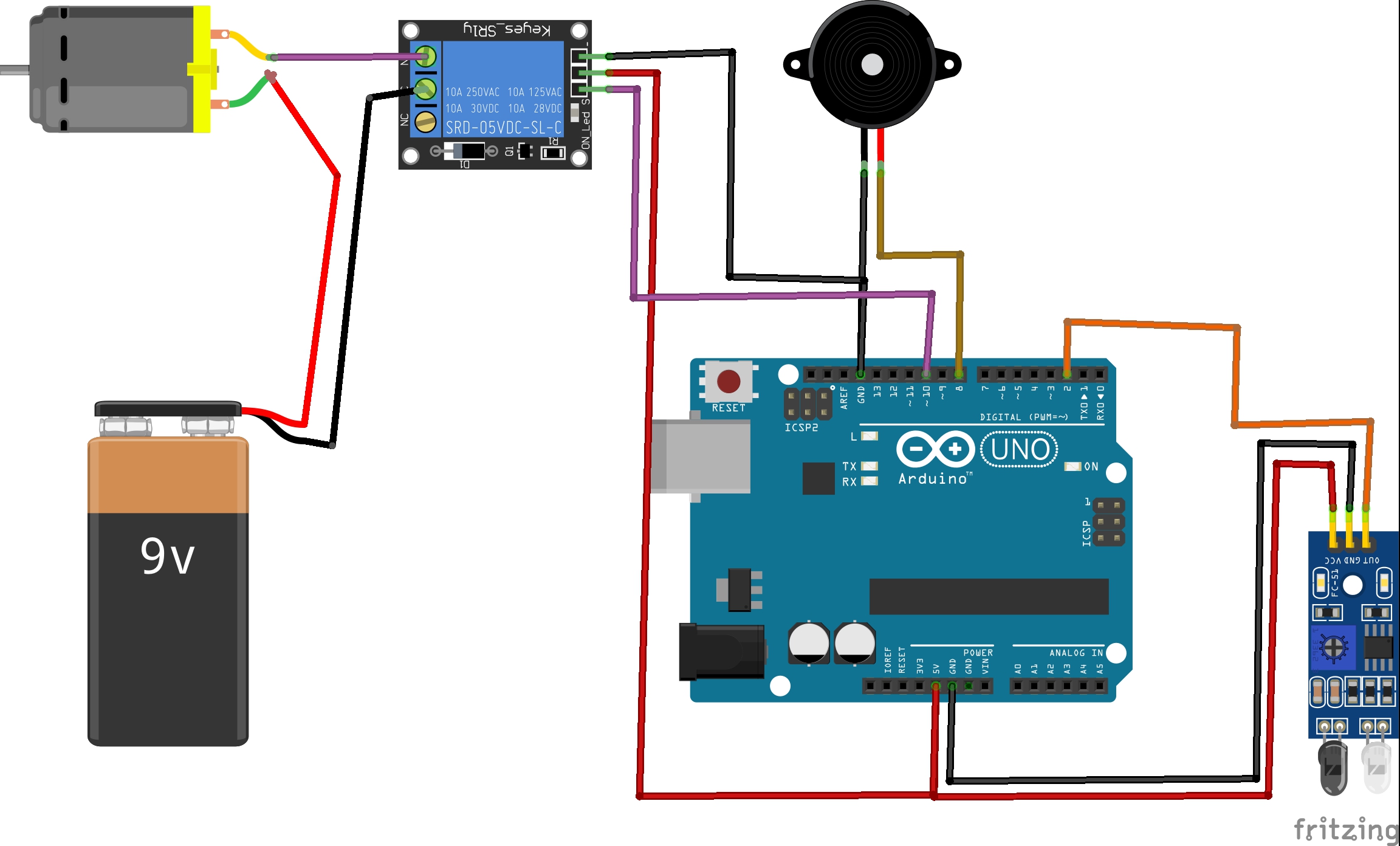
Pin Connections:
IR Sensor:
- VCC: Connect to 5V pin on Arduino
- GND: Connect to the GND pin on the Arduino
- OUT: Connect to digital pin 2 on Arduino
Buzzer:
- Positive (longer leg): Connect to digital pin 8 on Arduino
- Negative (shorter leg): Connect to GND pin on Arduino
Relay Module:
- VCC: Connect to 5V pin on Arduino
- GND: Connect to the GND pin on the Arduino
- IN: Connect to digital pin 10 on Arduino
// Define pin connections
const int irSensorPin = 2; // Pin connected to the IR sensor
const int relayPin = 10;    // Pin connected to the relay to control relay
const int buzzer = 8;     // Pin connected to the buzzer

void setup() {
  // Initialize serial communication for debugging
  Serial.begin(9600);

  // Set pin modes
  pinMode(irSensorPin, INPUT);
  pinMode(relayPin, OUTPUT);
pinMode(buzzer, OUTPUT);

  // Ensure the motor is off initially
  digitalWrite(relayPin, LOW);
  digitalWrite(buzzer, LOW);
}

void loop() {
  // Read the IR sensor value
  int sensorValue = digitalRead(irSensorPin);

  // Debugging: print the sensor value
  Serial.println(sensorValue);

  // If the sensor detects an open eye (sensor value high), turn the motor on
  if (sensorValue == HIGH) {
    digitalWrite(relayPin, HIGH);
    Serial.println("Eye Open - Motor ON");
  }
  // If the sensor detects a closed eye (sensor value low), turn the motor off
  else {
    digitalWrite(relayPin, LOW);
    digitalWrite(buzzer, HIGH);
    Serial.println("Eye Closed - Motor OFF");
  }

  // Add a small delay to avoid bouncing
  delay(100);
}