Bionic Hand project utilizes an Arduino Uno, flex sensors, and servo motors to create a robotic hand that mimics real human movement. Flex sensors are placed on a glove to detect finger movements. When you bend your fingers, the flex sensors change their resistance, sending signals to the Arduino. Then the Arduino Uno, a microcontroller, processes these signals and sends commands to the servo motors. Servo motors, which act as the muscles of the bionic hand, move the fingers based on the signals received from the Arduino. This project is excellent for learning how to use Arduino to control sensors and motors. It demonstrates how electronic components work together: the flex sensors measure movement, the Arduino processes the information, and the servo motors create motion. This hands-on project helps you understand the basics of robotics and prosthetics, offering a simple and affordable way to build a functional prosthetic hand. Working on this project shows how basic electronics can be used to create useful tools for people.
The components used in this project are:
- Arduino UNO with cable
- Flex Sensor 2.2 inch x 5
- Servo Motor x 5
- Resistor 10k ohm x 5
- Fishing String
- Gloves
- Small Breadboard
- Male to Female Jumper Wires x 15
- Male to Male Jumper Wires x 30
Featured Image:

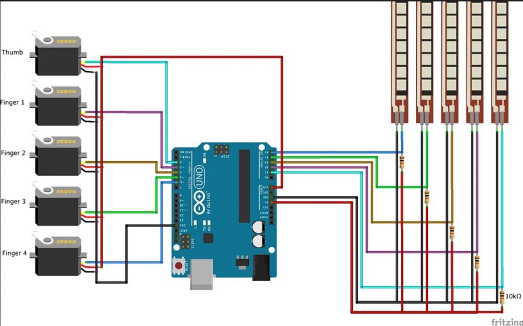
Pin Connection:
For Flex Sensor:
- Flex Sensor 1: GND to one end, other ends to A1 with a 10k ohm resistor to 5V
- Flex Sensor 2: GND to one end, other ends to A2 with a 10k ohm resistor to 5V
- Flex Sensor 3: GND to one end, other ends to A3 with a 10k ohm resistor to 5V
- Flex Sensor 4: GND to one end, other ends to A4 with a 10k ohm resistor to 5V
- Flex Sensor 5: GND to one end, other ends to A5 with a 10k ohm resistor to 5V
For Servo Motor:
- Servo Motor 1: 5V to red wire, GND to black wire, Signal -> Arduino Digital Pin 2
- Servo Motor 2: 5V to red wire, GND to black wire, Signal -> Arduino Digital Pin 3
- Servo Motor 3: 5V to red wire, GND to black wire, Signal -> Arduino Digital Pin 4
- Servo Motor 4: 5V to red wire, GND to black wire, Signal -> Arduino Digital Pin 5
- Servo Motor 5: 5V to red wire, GND to black wire, Signal -> Arduino Digital Pin 6
Calibration:
After uploading the code, open the serial monitor and check the flex sensor reading. Take separate readings with your hand open and close. If any difference is found in the readings (provided in the code) make changes in the code in the map function.
Circuit Diagram:
Code:
// Test your Idle and close reading of your flex sensor and change accordingly
//Idle  790--835--793--859--827--
//Close 880--844--802--866--831--

#include <Servo.h>

int flex1 = A1;
int flex2 = A2;
int flex3 = A3;
int flex4 = A4;
int flex5 = A5;

Servo servo1;
Servo servo2;
Servo servo3;
Servo servo4;
Servo servo5;

void setup()
{
  Serial.begin(9600);
  servo1.attach(2);
  servo2.attach(3);
  servo3.attach(4);
  servo4.attach(5);
  servo5.attach(6);
}


void loop()
{
  int flex1_pos;
  int servo1_pos;
  flex1_pos = analogRead(flex1);
  servo1_pos = map(flex1_pos, 840, 900, 180, 0);
  servo1_pos = constrain(servo1_pos, 180, 0);
  servo1.write(servo1_pos);

  int flex2_pos;
  int servo2_pos;
  flex2_pos = analogRead(flex2);
  servo2_pos = map(flex2_pos, 879, 882, 0, 180);
  servo2_pos = constrain(servo2_pos, 0, 180);
  servo2.write(servo2_pos);


  int flex3_pos;
  int servo3_pos;
  flex3_pos = analogRead(flex3);
  servo3_pos = map(flex3_pos, 828, 824, 180, 0);
  servo3_pos = constrain(servo3_pos, 180, 0);
  servo3.write(servo3_pos);

  int flex4_pos;
  int servo4_pos;
  flex4_pos = analogRead(flex4);
  servo4_pos = map(flex4_pos, 874, 878, 0, 180);
  servo4_pos = constrain(servo4_pos, 0, 180);
  servo4.write(servo4_pos);

  int flex5_pos;
  int servo5_pos;
  flex5_pos = analogRead(flex5);
  servo5_pos = map(flex5_pos, 855, 851, 180, 0);
  servo5_pos = constrain(servo5_pos, 180, 0);
  servo5.write(servo5_pos);


  /*
Serial.print(servo1_pos);
Serial.print("--");
Serial.print(servo2_pos);
Serial.print("--");
Serial.print(servo3_pos);
Serial.print("--");
Serial.print(servo4_pos);
Serial.print("--");
Serial.print(servo5_pos);
Serial.println("--");
*/

Serial.print(flex1_pos);
Serial.print("--");
Serial.print(flex2_pos);
Serial.print("--");
Serial.print(flex3_pos);
Serial.print("--");
Serial.print(flex4_pos);
Serial.print("--");
Serial.print(flex5_pos);
Serial.println("--");

  delay(300);


}


