Project Description:
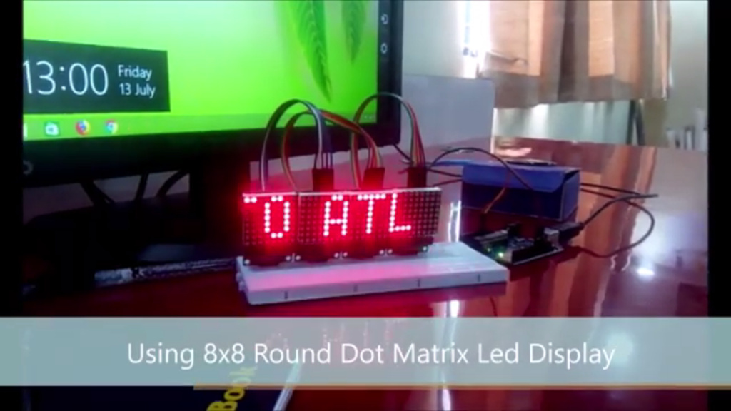
This project involves creating a welcome screen using four 8×8 LED matrix displays controlled by an Arduino. The LED matrices will display a scrolling “WELCOME TO ATL LAB” message. This project is good as an introduction to working with LED matrices and can be used for various applications such as digital message displays, clocks, and banners.
Components Required:
- Arduino Uno with cable
- 8×8 LED Matrix Modules MAX7219
- Jumper Wires
- Jumper wires – Male to Female x 5
– Female to Female x 15
Learning Outcomes
- Introduction to LED Matrices: Understand how to work with 8×8 LED matrices and control them using an Arduino.
- Basic Circuit Design: Learn how to connect multiple LED matrices in a daisy-chain configuration.
- Programming: Gain experience in using the MD_MAX72XX and MD_Parola libraries for controlling LED matrices.
- DIY Display Projects: Encourage creativity and problem-solving by allowing students to create their own LED displays for various applications.
This project will result in a visually engaging welcome screen, providing an excellent introduction to working with LED matrices, Arduino programming, and digital displays.
IMAGE:
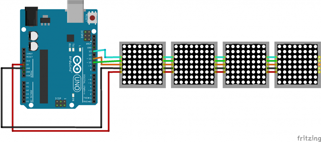
Connections:
The four LED matrices are connected in a chain configuration. The first matrix connects to the Arduino, and each subsequent matrix connects to the previous one.
Arduino to First LED Matrix:
- VCC of Matrix to 5V of Arduino
- GND of Matrix to GND of Arduino
- DIN of Matrix to Pin 11 of Arduino
- CS of Matrix to Pin 10 of Arduino
- CLK of Matrix to Pin 13 of Arduino
Subsequent Matrices:
- VCC to VCC of the previous matrix
- GND to GND of the previous matrix
- DIN of the second matrix to DOUT of the first matrix
- CS to CS of the previous matrix
- CLK to CLK of the previous matrix
CIRCUIT DIAGRAM:
NOTE: Before uploading and running the code IN ARDUINO IDE:
Go to > Sketch > Include Library > Manage Libraries… > Type the library name
OR Go to > Sketch > Include Library > Add .ZIP Library… download the zip library from the given link below.
MD_Parola library – https://github.com/MajicDesigns/MD_Parola
MD_MAX72XX library – https://github.com/MajicDesigns/MD_MAX72XX
CODE:
#include <MD_Parola.h>
#include <MD_MAX72XX.h>
#include <SPI.h>

// Define the number of devices we have in the chain
#define MAX_DEVICES 4

// Define hardware type, size, and pins
#define HARDWARE_TYPE MD_MAX72XX::FC16_HW
#define DATA_PIN 11
#define CS_PIN 10
#define CLK_PIN 13

// Create a new instance of the MD_Parola class with hardware SPI connection
MD_Parola myDisplay = MD_Parola(HARDWARE_TYPE, CS_PIN, MAX_DEVICES);

void setup() {
  // Initialize the object
  myDisplay.begin();

  // Set the intensity (brightness) of the display (0-15)
  myDisplay.setIntensity(0);

  // Clear the display
  myDisplay.displayClear();

  // Set the text alignment
  myDisplay.setTextAlignment(PA_CENTER);

  // Set the scroll speed (time in milliseconds between updates)
  myDisplay.setSpeed(100);
}

void loop() {
  // Set the text to be displayed
  myDisplay.displayText("WELCOME TO ATL LAB", PA_CENTER, myDisplay.getSpeed(), 0, PA_SCROLL_LEFT, PA_SCROLL_LEFT);

  // Animate the display
  while (!myDisplay.displayAnimate()) {
    // Do nothing while the text is scrolling
  }
}


