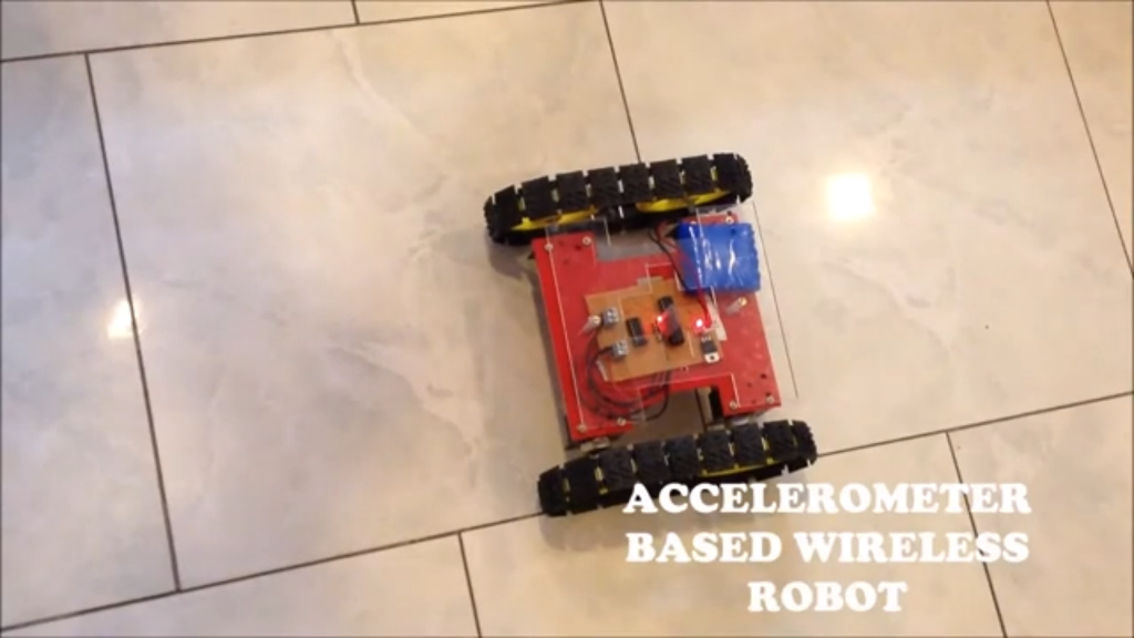
Creating an Accelerometer-based wireless robot using an Arduino Uno, motor driver, and Bluetooth module is a project that combines electronics, programming, wireless communication, and the use of the accelerometer. Arduino Uno is the main micro-controller that helps in all the processing. A motor driver L298N is used to control the motors of the robot, providing the necessary current and voltage to drive the motors forward, backward, left, or right. The Bluetooth module HC-05 enables wireless communication between the Arduino and the controlling device. This project not only offers a practical application of wireless communication and motor control but also provides a platform to learn about circuit design, coding, and the integration of hardware components. It is an excellent way for hobbyists and students to explore the world of robotics and automation, providing a hands-on experience with real-time problem-solving and creativity in building and customization.
The components used in this project are:
- Arduino UNO with cable
- Motor Driver L298N
- Bluetooth Module HC-05
- BO motor x 4
- Jumper Wires – Male to Male x 14
Male to Female x 8 - Breadboard Small
- Red LED
- Resistor 220 ohm
- Toggle Switch
Featured Image:
Android App link requires to control the car:
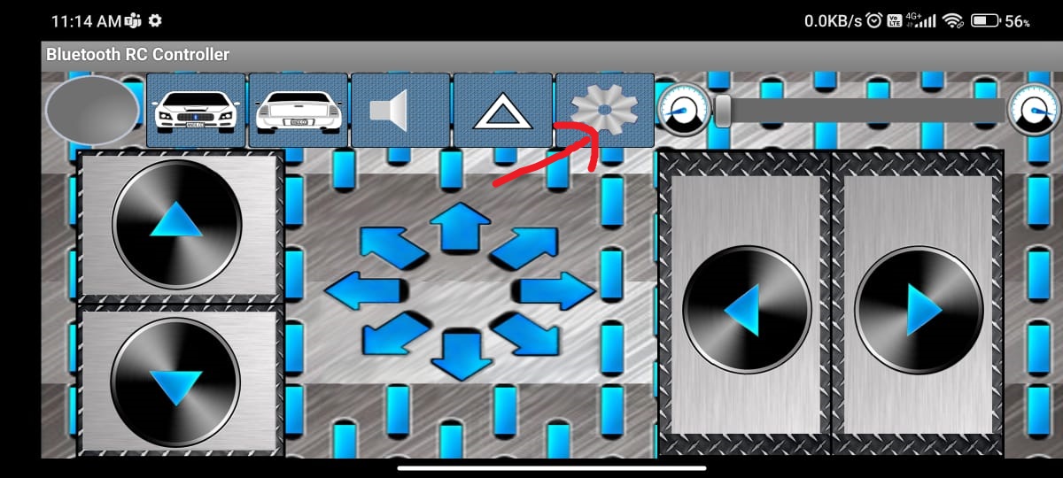
After installing the app make the following changes:
Step 1: Click on the setting button.
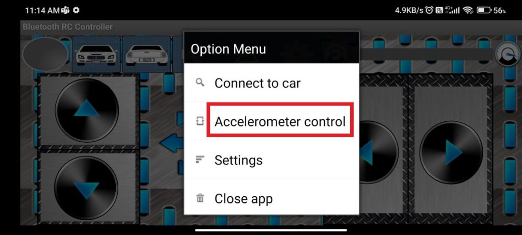
Step 2: After clicking on the setting button, the Option Menu occurs. Click on the ” Accelerometer control” option.
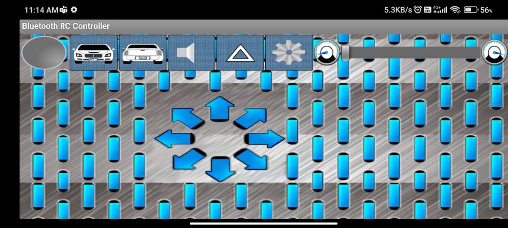
Step 3: The following interface will occur.
Bluetooth Connection Process:
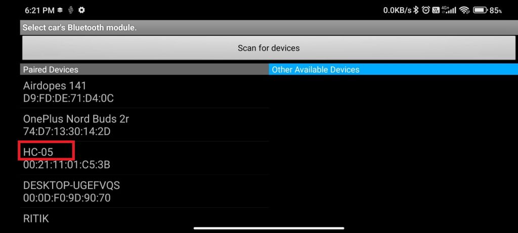
Step 1: Turn ON your mobile Bluetooth and search for HC-05.
Step 2: When HC-05 occurs, Click on it and enter 1234 as the pairing pin.
Step 3: Upon Successfully paired, Open the Android app.
Step 4: Now, click on the setting button shown below.

Step 5: After that, click on the “Connect to Car” option from the “Option Menu”.
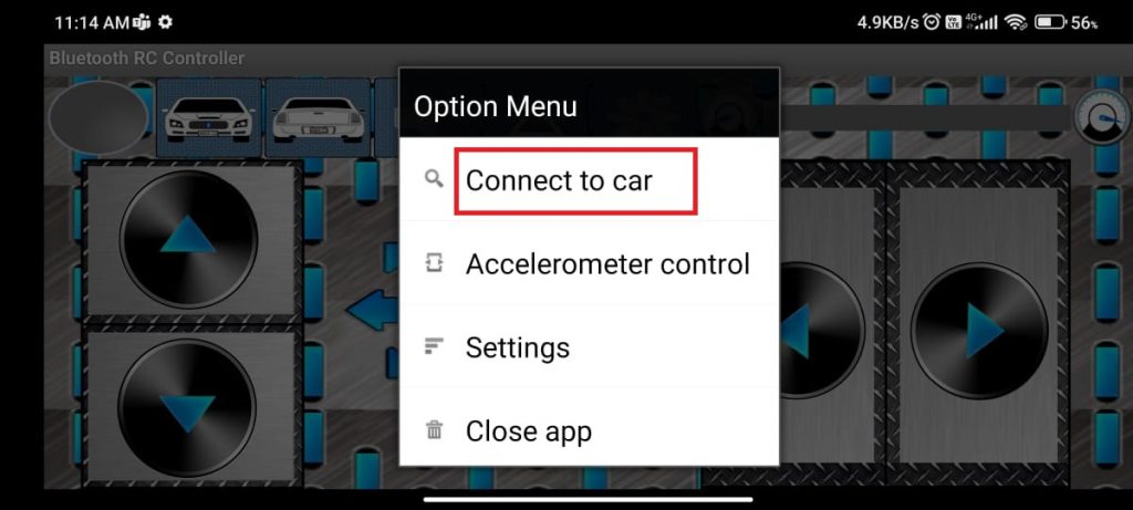
Step 6: Then, Click on the “HC-05” option. The Green Color indicates that the robot is connected.
After completing the above steps, tilt the phone to move the robot accordingly.
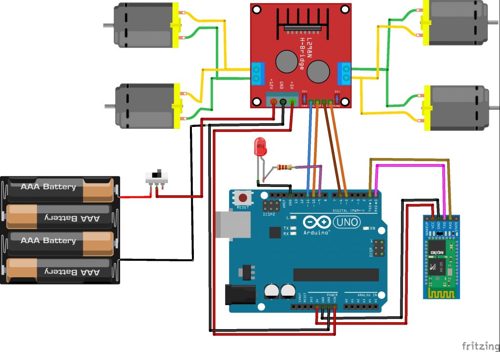
Pin Connection:
Motor Driver (L298N):
- IN1 (Motor A Input 1): Connect to Arduino digital pin 11
- IN2 (Motor A Input 2): Connect to Arduino digital pin 10
- IN3 (Motor B Input 1): Connect to Arduino digital pin 6
- IN4 (Motor B Input 2): Connect to Arduino digital pin 5
- VCC: Connected to Arduino 5V pin.
- GND: Connected to Arduino GND pin.
- Motor Power: Connected to an external power supply suitable for your motors (e.g., 9V or 12V).
Bluetooth Module (HC-05):
- VCC: Connected to Arduino 5V pin.
- GND: Connected to Arduino GND pin.
- TX: Connect to digital pin RX(0)
- RX: Connect to digital pin TX(1)
LED:
- Anode (longer leg): Connect to a current-limiting resistor 220 ohms and then to a digital pin 9
- Cathode (shorter leg): Connect directly to Arduino GND.
CIrcuit Diagram:
Code:
#define in1 11 //L298n Motor Driver pins.
#define in2 10
#define in3 6
#define in4 5
#define LED 9
int command; //Int to store app command state.
int Speed = 255; // 0 - 255.
int Speedsec;
int buttonState = 0;
int lastButtonState = 0;
int Turnradius = 0; //Set the radius of a turn, 0 - 255 Note:the robot will malfunction if this is higher than int Speed.
int brakeTime = 5;
int brkonoff = 1; //1 for the electronic braking system, 0 for normal.

void setup() {
  pinMode(in1, OUTPUT);
  pinMode(in2, OUTPUT);
  pinMode(in3, OUTPUT);
  pinMode(in4, OUTPUT);
  pinMode(LED, OUTPUT); //Set the LED pin.
  Serial.begin(9600);  //Set the baud rate to your Bluetooth module.

}

void loop() {
  if (Serial.available() > 0) {
    command = Serial.read();
    Stop(); //Initialize with motors stoped.
    switch (command) {
      case 'F':
        forward();
        Serial.println("F");
        break;
      case 'B':
        back();
        Serial.println("B");
        break;
      case 'L':
        left();
        break;
      case 'R':
        right();
        break;
      case 'G':
        forwardleft();
        break;
      case 'I':
        forwardright();
        break;
      case 'H':
        backleft();
        break;
      case 'J':
        backright();
        break;
      case '0':
        Speed = 65;
        break;
      case '1':
        Speed = 85;
        break;
      case '2':
        Speed = 105;
        break;
      case '3':
        Speed = 125;
        break;
      case '4':
        Speed = 145;
        break;
      case '5':
        Speed = 165;
        break;
      case '6':
        Speed = 195;
        break;
      case '7':
        Speed = 215;
        break;
      case '8':
        Speed = 230;
        break;
      case '9':
        Speed = 243;
        break;
      case 'q':
        Speed = 255;
        break;
      case 'W':
        analogWrite(LED,190);
        break;
      case 'w':
        digitalWrite(LED,LOW);
        break;
    }
    Speedsec = Turnradius;
    if (brkonoff == 1) {
      brakeOn();
    } else {
      brakeOff();
    }
  }
}

void forward() {
  analogWrite(in1, Speed);
  analogWrite(in3, Speed);
}

void back() {
  analogWrite(in2, Speed);
  analogWrite(in4, Speed);
}

void right() {
  analogWrite(in3, Speed);
  analogWrite(in2, Speed);
}

void left() {
  analogWrite(in4, Speed);
  analogWrite(in1, Speed);
}
void forwardright() {
  analogWrite(in1, Speedsec);
  analogWrite(in3, Speed);
}
void forwardleft() {
  analogWrite(in1, Speed);
  analogWrite(in3, Speedsec);
}
void backright() {
  analogWrite(in2, Speed);
  analogWrite(in4, Speedsec);
}
void backleft() {
  analogWrite(in2, Speedsec);
  analogWrite(in4, Speed);
}

void Stop() {
  analogWrite(in1, 0);
  analogWrite(in2, 0);
  analogWrite(in3, 0);
  analogWrite(in4, 0);
}

void brakeOn() {
  //Here's the future use: an electronic braking system!
  // read the pushbutton input pin:
  buttonState = command;
  // compare the buttonState to its previous state
  if (buttonState != lastButtonState) {
    // if the state has changed, increment the counter
    if (buttonState == 'S') {
      if (lastButtonState != buttonState) {
        digitalWrite(in1, HIGH);
        digitalWrite(in2, HIGH);
        digitalWrite(in3, HIGH);
        digitalWrite(in4, HIGH);
        delay(brakeTime);
        Stop();
      }
    }
    // save the current state as the last state,
    //for next time through the loop
    lastButtonState = buttonState;
  }
}
void brakeOff() {

}


