The Pollution Reduction Machine is designed to improve air quality by actively monitoring pollution levels and responding accordingly. Utilizing simple yet effective components such as an Arduino Uno, an I2C LCD display, a relay module, a water pump, and an MQ2 gas sensor, this project provides a practical solution to reduce air pollutants.
Working:
The system continuously monitors the air quality using the MQ2 gas sensor. When the sensor detects that pollution levels exceed a predefined threshold, it triggers the relay to activate the water pump. This disperses water into the air, helping to reduce the concentration of pollutants. The current air quality index (AQI) is displayed on the LCD, providing real-time updates.
Components Used:
- Arduino Uno x1
- I2C LCD Display x1
- Relay Module x1
- Water Pump x1
- MQ2 Gas Sensor x1
- Breadboard and Jumper Wires
Component Description:
- Arduino Uno: A microcontroller board based on the ATmega328P.
- I2C LCD Display: An LCD that communicates with the Arduino using the I2C protocol, making it easy to interface.
- Relay Module: An electrically operated switch that allows the Arduino to control high-power devices like the water pump.
- Water Pump: A small pump used to spray water.
- MQ2 Gas Sensor: Capable of detecting smoke, methane, and other gases.
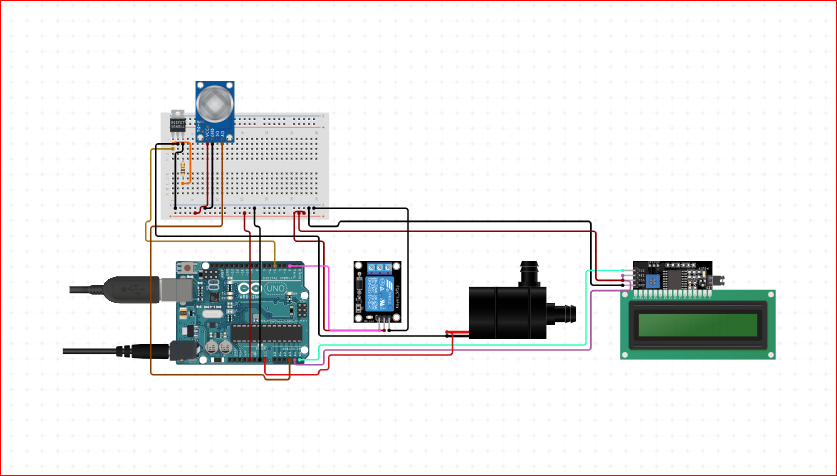
Circuit Connection:
- MQ2 Gas Sensor:
- VCC to 5V
- GND to GND
- Analog Output (A0) to A3 on Arduino
- Relay Module:
- VCC to 5V
- GND to GND
- IN to digital pin 2 on Arduino
- COM to one terminal of the water pump
- NO (Normally Open) to power source (connected in series with the water pump)
- Water Pump:
- One terminal to COM of relay
- Other terminal to ground of the power source
- LCD I2C:
- SDA to A4
- SCL to A5
- VCC to 5V
- GND to GND
#include <Wire.h>
#include <LiquidCrystal_I2C.h>

// Define the LCD I2C address and dimensions
LiquidCrystal_I2C lcd(0x27, 16, 2);

// Pin Definitions
const int mq2Pin = A3;    // MQ2 gas sensor analog pin
const int relayPin = 2;   // Relay module pin

// Threshold for MQ2 sensor to trigger water pump
const int gasThreshold = 300;

void setup() {
  // Initialize the LCD
  lcd.begin();
  lcd.backlight();
  lcd.setCursor(0, 0);
  lcd.print("Air Quality:");

  // Initialize Serial Monitor
  Serial.begin(9600);

  // Initialize pin modes
  pinMode(mq2Pin, INPUT);
  pinMode(relayPin, OUTPUT);

  // Initial state for relay (off)
  digitalWrite(relayPin, LOW);
}

void loop() {
  // Read the MQ2 gas sensor value
  int gasValue = analogRead(mq2Pin);

  // Convert gas value to a rough AQI value
  int aqiValue = map(gasValue, 0, 1023, 0, 500);  // Mapping gas sensor value to AQI range 0-500

  // Display the AQI value on the LCD
  lcd.setCursor(0, 1);
  lcd.print("AQI: ");
  lcd.print(aqiValue);

  // Print the gas value and AQI value to the Serial Monitor
  Serial.print("Gas Level: ");
  Serial.print(gasValue);
  Serial.print(" - AQI: ");
  Serial.println(aqiValue);

  // Check if the AQI value exceeds the threshold
  if (aqiValue > gasThreshold) {
    // Turn on the relay (activate water pump)
    digitalWrite(relayPin, HIGH);
    lcd.setCursor(10, 1);
    lcd.print("Pump ON ");
  } else {
    // Turn off the relay (deactivate water pump)
    digitalWrite(relayPin, LOW);
    lcd.setCursor(10, 1);
    lcd.print("Pump OFF");
  }

  // Wait for a short period before next reading
  delay(1000);
}


