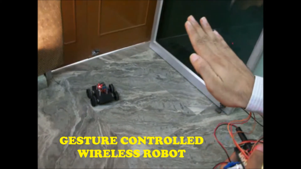
The gesture-controlled wireless robot project utilizes an Arduino Nano to create a car controlled through hand gestures. It incorporates two NRF24L01 modules for wireless communication—one on the car and one on the controller. The controller employs an MPU6050 accelerometer and gyroscope to detect hand movements. When tilted, the MPU6050 sends signals to the Arduino Nano on the controller, which transmits commands via NRF24L01 to the Arduino Nano on the car. The car’s Arduino processes these commands using an L293D motor driver IC to control four BO motors attached to the wheels, enabling movements based on gestures: forward, backward, left, or right. A 7805 voltage regulator ensures a stable 5V power supply. Gesture-controlled wireless robot project showcases robotics, wireless communication, and touchless interface development, benefiting individuals with mobility issues. It allows robotics enthusiasts to gain hands-on experience with microcontrollers practically and engagingly.
Components used in this project are:
- Arduino Nano x 2 with cable
- Nrf24l01 Module x 2
- MPU6050 Accelerometer and Gyroscope
- L293D IC
- BO Motor & Wheel x 4
- Zero PCB
- Female Header
- 10uF capacitor
- 7805 Voltage Regulator
- Male to Female jumper wires x 15
- Male to Male jumper wires x 50
Featured Image:
Connection Pins of Transmitter Circuit:
- Power Supply:
- Connect the 9V battery’s positive terminal to the VIN pin on the Arduino Nano.
- Connect the 9V battery’s negative terminal to the GND pin on the Arduino Nano.
- NRF24L01 Module:
- VCC (3.3V): Connect to the 3.3V pin on the Arduino Nano.
- GND: Connect to the GND pin on the Arduino Nano.
- CE: Connect to Digital Pin 8 on the Arduino Nano.
- CSN: Connect to Digital Pin 9 on the Arduino Nano.
- SCK: Connect to Digital Pin 13 on the Arduino Nano.
- MOSI: Connect to Digital Pin 11 on the Arduino Nano.
- MISO: Connect to Digital Pin 12 on the Arduino Nano.
- Add a 10uF capacitor between VCC and GND near the NRF24L01 module for stability.
- MPU6050 Accelerometer and Gyroscope:
- VCC: Connect to the 3.3V pin on the Arduino Nano.
- GND: Connect to the GND pin on the Arduino Nano.
- SCL: Connect to the A5 pin on the Arduino Nano.
- SDA: Connect to the A4 pin on the Arduino Nano.
- INT: Connect to Digital Pin 2 on the Arduino Nano.
Transmitter Circuit Diagram:
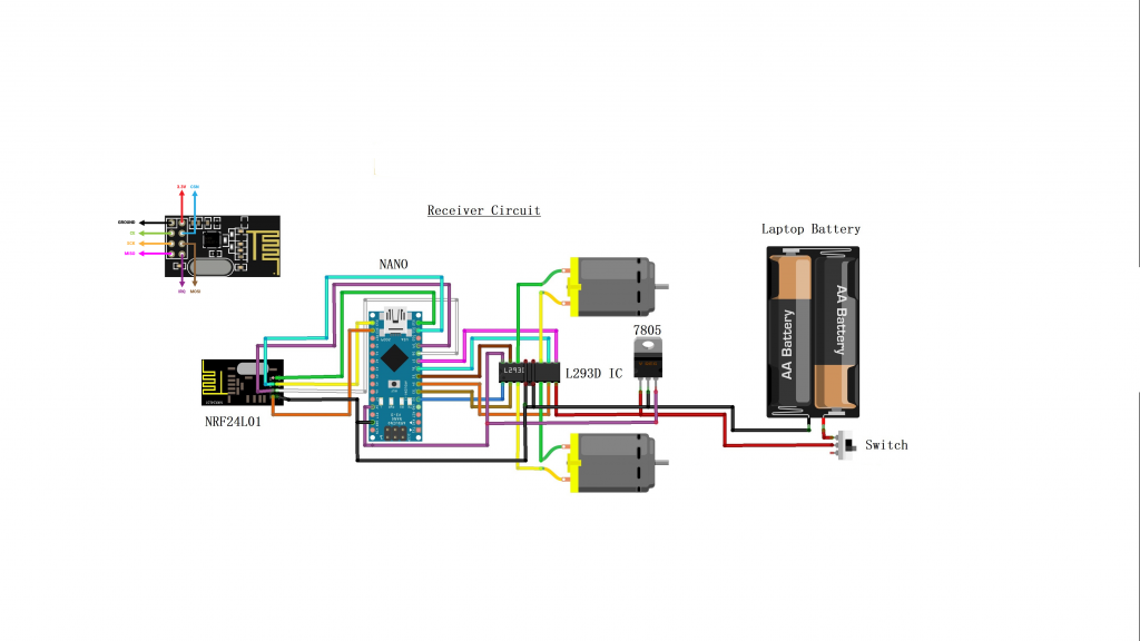
Connection Pins of Receiver Circuit:
- NRF24L01
- GND to GND
- VCC to 3.3V
- CE to D8
- CSN to D9
- SCK to D13
- MOSI to D11
- MISO to D12
L293D Motor Driver IC
- Pin 1 (Enable 1,2) to D2
- Pin 2 (Input 1) to D3
- Pin 7 (Input 2) to D4
- Pin 3 (Output 1) to Motor 1 Terminal 1
- Pin 6 (Output 2) to Motor 1 Terminal 2
- Pin 9 (Enable 3,4) to D7
- Pin 10 (Input 3) to D5
- Pin 15 (Input 4) to D5
- Pin 11 (Output 3) to Motor 2 Terminal 1
- Pin 14 (Output 4) to Motor 2 Terminal 2
Motors
- Motor 1 connected to L293D Output 1 and Output 2
- Motor 2 connected to L293D Output 3 and Output 4
7805 Voltage Regulator
- Input to Battery Positive Terminal
- GND to Battery Negative Terminal
- Output to Arduino Nano 5V
Battery Pack (Laptop Battery)
- Positive Terminal to Switch
- Switch to 7805 Voltage Regulator Input
- Negative Terminal to GND
Switch
- Connected between Battery Positive Terminal and 7805 Voltage Regulator Input
Receiver Circuit Diagram:
Arduino Transmitter Code:
#include <SPI.h>        //SPI library for communicate with the nRF24L01+
#include "RF24.h"       //The main library of the nRF24L01+
#include "Wire.h"       //For communicate
#include "I2Cdev.h"     //For communicate with MPU6050
#include "MPU6050.h"    //The main library of the MPU6050


//Define the object to access and cotrol the Gyro and Accelerometer (We don't use the Gyro data)
MPU6050 mpu;
int16_t ax, ay, az;
int16_t gx, gy, gz;

//Define packet for the direction (X axis and Y axis)
int data[2];

//Define object from RF24 library - 9 and 10 are a digital pin numbers to which signals CE and CSN are connected.
RF24 radio(8,9);

//Create a pipe addresses for the communicate
const uint64_t pipe = 0xE8E8F0F0E1LL;

void setup(void){
  Serial.begin(9600);
  Wire.begin();
  mpu.initialize();              //Initialize the MPU object
  radio.begin();                 //Start the nRF24 communicate
  radio.openWritingPipe(pipe);   //Sets the address of the receiver to which the program will send data.
}

void loop(void){

  //With this function, the acceleration and gyro values of the axes are taken.
  //If you want to control the car axis differently, you can change the axis name in the map command.
  mpu.getMotion6(&ax, &ay, &az, &gx, &gy, &gz);

  //In two-way control, the X axis (data [0]) of the MPU6050 allows the robot to move forward and backward.
  //Y axis (data [0]) allows the robot to right and left turn.
  data[0] = map(ax, -17000, 17000, 300, 400 ); //Send X axis data
  data[1] = map(ay, -17000, 17000, 100, 200);  //Send Y axis data
  radio.write(data, sizeof(data));
}
Arduino Receiver Code:
#include <SPI.h>      //SPI library for communicate with the nRF24L01+
#include "RF24.h"     //The main library of the nRF24L01+

//Define enable pins of the Motors
const int enbA = 2;
const int enbB = 7;

//Define control pins of the Motors
//If the motors rotate in the opposite direction, you can change the positions of the following pin numbers
const int IN1 = 3;    //Right Motor (-)
const int IN2 = 4;    //Right Motor (+)
const int IN3 = 5;    //Left Motor (+)
const int IN4 = 6;    //Right Motor (-)

//Define variable for the motors speeds
//I have defined a variable for each of the two motors
//This way you can synchronize the rotation speed difference between the two motors
int RightSpd = 130;
int LeftSpd = 150;

//Define packet for the direction (X axis and Y axis)
int data[2];

//Define object from RF24 library - 9 and 10 are a digital pin numbers to which signals CE and CSN are connected
RF24 radio(8,9);

//Create a pipe addresses for the communicate
const uint64_t pipe = 0xE8E8F0F0E1LL;

void setup(){
  //Define the motor pins as OUTPUT
  pinMode(enbA, OUTPUT);
  pinMode(enbB, OUTPUT);
  pinMode(IN1, OUTPUT);
  pinMode(IN2, OUTPUT);
  pinMode(IN3, OUTPUT);
  pinMode(IN4, OUTPUT);

  Serial.begin(9600);
  radio.begin();                    //Start the nRF24 communicate
  radio.openReadingPipe(1, pipe);   //Sets the address of the transmitter to which the program will receive data.
  radio.startListening();
  }

void loop(){
  if (radio.available()){
    radio.read(data, sizeof(data));

    if(data[0] > 380){
      //forward
      analogWrite(enbA, RightSpd);
      analogWrite(enbB, LeftSpd);
      digitalWrite(IN1, HIGH);
      digitalWrite(IN2, LOW);
      digitalWrite(IN3, HIGH);
      digitalWrite(IN4, LOW);
    }

    if(data[0] < 310){
      //backward
      analogWrite(enbA, RightSpd);
      analogWrite(enbB, LeftSpd);
      digitalWrite(IN1, LOW);
      digitalWrite(IN2, HIGH);
      digitalWrite(IN3, LOW);
      digitalWrite(IN4, HIGH);
    }

    if(data[1] > 180){
      //left
      analogWrite(enbA, RightSpd);
      analogWrite(enbB, LeftSpd);
      digitalWrite(IN1, HIGH);
      digitalWrite(IN2, LOW);
      digitalWrite(IN3, LOW);
      digitalWrite(IN4, HIGH);
    }

    if(data[1] < 110){
      //right
      analogWrite(enbA, RightSpd);
      analogWrite(enbB, LeftSpd);
      digitalWrite(IN1, LOW);
      digitalWrite(IN2, HIGH);
      digitalWrite(IN3, HIGH);
      digitalWrite(IN4, LOW);
    }

    if(data[0] > 330 && data[0] < 360 && data[1] > 130 && data[1] < 160){
      //stop car
      analogWrite(enbA, 0);
      analogWrite(enbB, 0);
    }
  }
}


