The Smart Blind Shoe is like a high-tech guide for people who can’t see well. It uses special parts like tiny vibrating motors, a sensor that detects how far things are, a buzzer that makes noise, and a small computer called Arduino. When you wear these shoes, they can feel if there’s something in your way and tell you about it with vibrations and sounds. This helps you walk safely and know what’s around you even if you can’t see it. It’s designed to be easy to use and helps people with visual challenges move around confidently on their own.
Components:
- Ultrasonic Sensor: Detects obstacles by emitting ultrasonic waves and measuring the distance to objects.
- Vibro Motor: Provides haptic feedback to the user by vibrating when an obstacle is detected.
- Buzzer: Emits an audible sound to alert the user to obstacles.
- Arduino: Processes data from the ultrasonic sensor and controls the vibro motor and buzzer.
Working Principle:
- Obstacle Detection: The ultrasonic sensor continuously emits ultrasonic waves. When these waves hit an obstacle, they bounce back to the sensor.
- Distance Calculation: The Arduino calculates the distance to the obstacle based on the time taken for the waves to return.
- Alert Mechanism: If an obstacle is detected within a predefined range, the Arduino activates the vibro motor and the buzzer. The intensity of the vibration and the frequency of the buzzer can be adjusted based on the proximity of the obstacle.
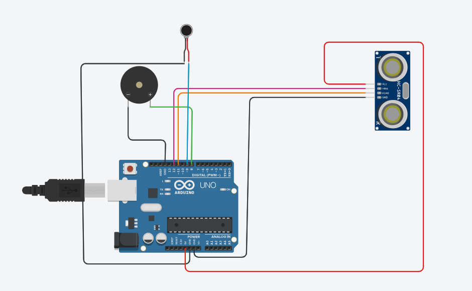
Implementation/Circuit:
- Hardware Setup:
- Connect the ultrasonic sensor to the Arduino’s digital pins.
- Connect the vibro motor to one of the PWM (Pulse Width Modulation) pins on the Arduino for variable intensity control.
- Connect the buzzer to another digital pin on the Arduino.
- Programming:
- Write a program for the Arduino to read the data from the ultrasonic sensor.
- Implement logic to determine when to activate the Vibro motor and buzzer based on the distance to detected obstacles.
CODE
#include <NewPing.h>

#define TRIGGER_PIN  12
#define ECHO_PIN     11
#define MAX_DISTANCE 200 // Maximum distance to detect (in cm)
#define VIBRO_PIN     9
#define BUZZER_PIN    8

NewPing sonar(TRIGGER_PIN, ECHO_PIN, MAX_DISTANCE);

void setup() {
  pinMode(TRIGGER_PIN, OUTPUT);
  pinMode(ECHO_PIN, INPUT);
  pinMode(VIBRO_PIN, OUTPUT);
  pinMode(BUZZER_PIN, OUTPUT);
}

void loop() {
  delay(50);
  unsigned int distance = sonar.ping_cm();

  if (distance > 0 && distance < 50) { // If obstacle detected within 50 cm
    digitalWrite(VIBRO_PIN, HIGH); // Turn on vibro motor
    digitalWrite(BUZZER_PIN, HIGH); // Turn on buzzer
  } else {
    digitalWrite(VIBRO_PIN, LOW); // Turn off vibro motor
    digitalWrite(BUZZER_PIN, LOW); // Turn off buzzer
  }
}
Advantages:
- Customizable: The system can be tailored to the specific needs of the user, such as adjusting the sensitivity or changing the alert mechanisms.
- Simple and Cost-Effective: Uses readily available components and straightforward programming.
- Increased Mobility: Helps visually impaired individuals move around more confidently and safely.


