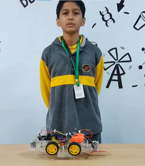
The Van Overloading Indicator is an essential safety system created to continuously monitor and report load conditions in vehicles. By utilizing a force sensor, this system accurately measures the weight of the cargo. It then uses a motor driver to control two motors, allowing it to adjust the vehicle’s performance based on the load. This real-time data collection and alert mechanism help prevent overloading, ensuring the van operates optimally and safely. This technology is crucial for students to grasp as it directly impacts vehicle safety, maintenance, and efficiency, providing a practical understanding of engineering principles in transportation systems.
Components:
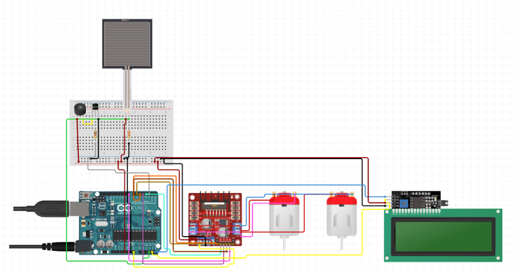
- Force Sensor: Detects the load applied to the van.
- Motor Driver: Controls two motors that simulate load movement.
- Two Motors: Represent the van’s load mechanism.
- Buzzer: Provides an audible alert when overloading is detected.
- I2C LCD Display: Shows real-time load status and alerts.
- Arduino Uno: Central microcontroller for data processing and control.
Setup and Installation:
- Connect the force sensor to the Arduino’s analog pin A0.
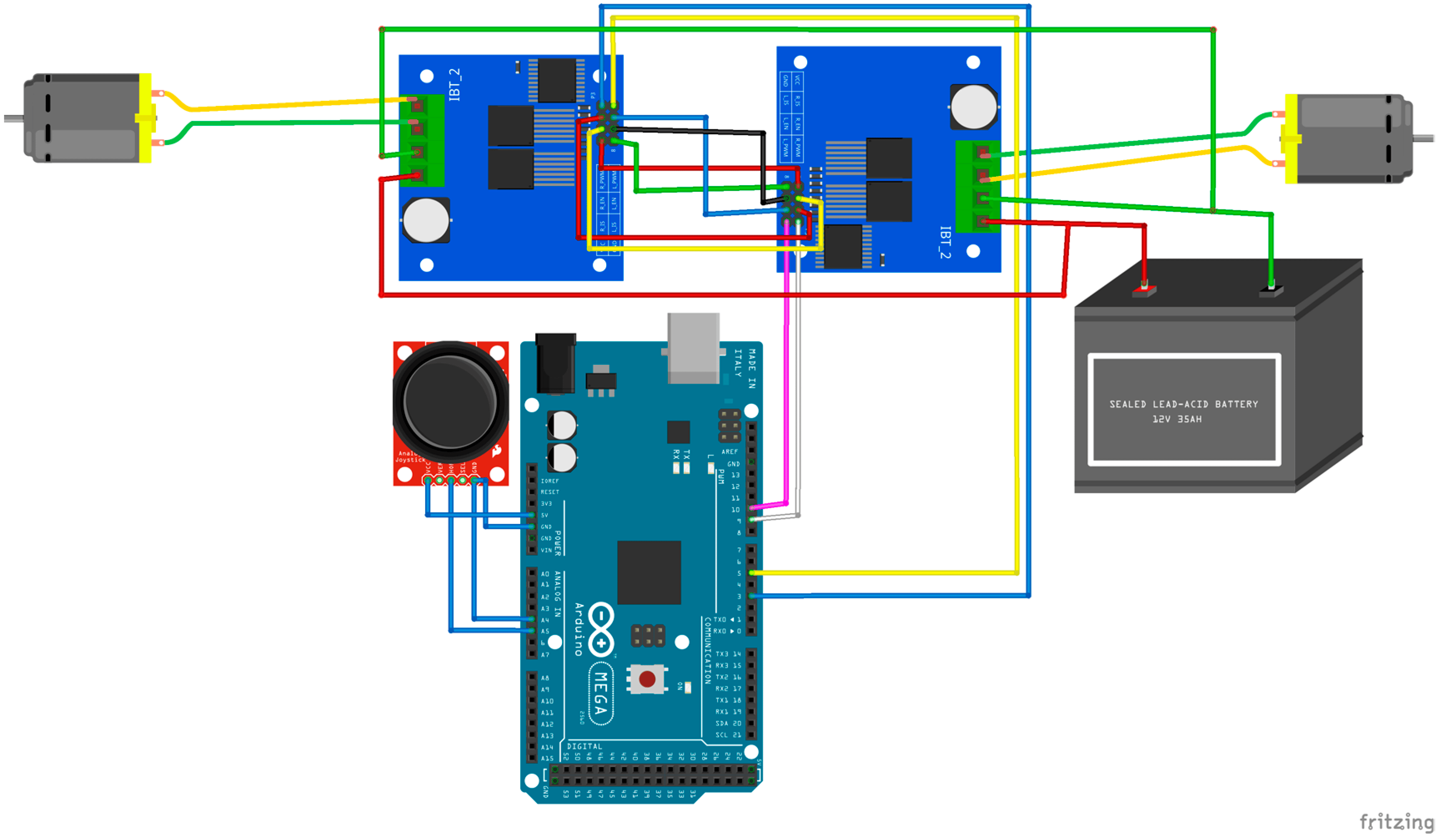
- Connect the motor driver to the Arduino and the motors to the motor driver.
- Connect the buzzer to the Arduino’s digital pin 8.
- Connect the I2C LCD display to the Arduino using the I2C interface (pins A4 for SDA and A5 for SCL).
- Power the Arduino via a USB cable or external power source.
Operation/Circuit:
- The force sensor continuously monitors the load.
- The Arduino processes the sensor data and displays the load status on the I2C LCD.
- If the load exceeds a predefined threshold for a set duration, the system triggers the buzzer and displays an “Overload” message.
- The motor driver controls the motors to simulate load changes.
CODE
#include <Wire.h>
#include <LiquidCrystal_I2C.h>

// Initialize the LCD with I2C address and dimensions
LiquidCrystal_I2C lcd(0x27, 16, 2);

const int forceSensorPin = A3;
const int motor1EnA = 5;
const int motor1In1 = 3;
const int motor1In2 = 4;
const int motor2EnB = 6;
const int motor2In3 = 7;
const int motor2In4 = 8;
const int buzzerPin = 2;
const int threshold = 500;  // Overload threshold value
const unsigned long durationThreshold = 3000;  // Duration threshold in milliseconds

unsigned long overloadStartTime = 0;
bool overloadDetected = false;

void setup() {
  // Initialize the I2C communication for the LCD
  Wire.begin(A4, A5);

  // Initialize the LCD
  lcd.begin(16, 2);
  lcd.backlight();

  // Initialize motor and buzzer pins
  pinMode(motor1EnA, OUTPUT);
  pinMode(motor1In1, OUTPUT);
  pinMode(motor1In2, OUTPUT);
  pinMode(motor2EnB, OUTPUT);
  pinMode(motor2In3, OUTPUT);
  pinMode(motor2In4, OUTPUT);
  pinMode(buzzerPin, OUTPUT);

  // Initialize serial communication for debugging
  Serial.begin(9600);
}

void loop() {
  int forceValue = analogRead(forceSensorPin);
  Serial.println(forceValue);

  lcd.clear();
  lcd.setCursor(0, 0);
  lcd.print("Load: ");
  lcd.print(forceValue);

  if (forceValue > threshold) {
    if (!overloadDetected) {
      overloadStartTime = millis();
      overloadDetected = true;
    } else if (millis() - overloadStartTime >= durationThreshold) {
      lcd.setCursor(0, 1);
      lcd.print("Overload");
      digitalWrite(buzzerPin, HIGH);
    }
  } else {
    overloadDetected = false;
    digitalWrite(buzzerPin, LOW);
  }

  delay(500);
}
Testing and Calibration:
- Conduct thorough testing to ensure the system accurately detects and reports load conditions.
- Calibrate the force sensor for precise measurements.
- Test the alarm system to confirm it alerts users effectively at the set thresholds.
Benefits:
- Provides real-time monitoring of vehicle load.
- Enhances safety by preventing overloading in vehicles.
- Promotes timely action through audible and visual alerts, minimizing risks.
- Supports optimal vehicle performance and prevents damage.
- Educates users on safe load management practices.

