Controlling LEDs using an IR (Infrared) remote control is a practical and versatile application that can be implemented using Arduino or similar microcontrollers. Here’s a comprehensive description of how to set up and use LED control via an IR remote:
Components Needed:
1. Arduino Board (e.g., Arduino Uno):
· Acts as the central controller to receive IR signals, decode them, and control the LEDs accordingly.
2. IR Receiver Module (e.g., TSOP38238):
· Detects infrared signals from the IR remote control and converts them into electrical signals that the Arduino can interpret.
3. IR Remote Control:
· Sends infrared signals that correspond to different commands (such as power on/off, brightness control, color change, etc.).
4. LEDs:
· Light Emitting Diodes used for visual output. These can be single LEDs, LED strips, or arrays, depending on your project requirements.
5. Transistors/MOSFETs (optional):
· Used as switching components if driving high-power LEDs or LED strips that require more current than the Arduino can directly provide.
Setup and Working Principle:
6. Hardware Connections:
· Connect the IR receiver module to the Arduino according to its datasheet or module documentation. Typically, this involves connecting the module’s output pin to a digital input pin on the Arduino.
7. LED Connections:
· Connect the LEDs to the Arduino’s digital output pins through current-limiting resistors. For high-power LEDs or LED strips, use transistors or MOSFETs to switch them on and off.
8. IR Remote Setup:
· Program the Arduino to recognize specific IR remote control commands. Libraries like IRremote.h simplify this process by providing functions to decode different IR protocols (e.g., NEC, Sony, etc.).
9. Operation:
· Point the IR remote control towards the IR receiver module connected to the Arduino. Press the buttons corresponding to the defined commands (e.g., power on/off, brightness adjustment). The Arduino decodes these signals and triggers the corresponding actions to control the LEDs.
Additional Features and Considerations:
· Multi-Function Remote: Utilize different buttons on the remote to control various LED behaviors such as color changes, animation modes, or preset lighting scenes.
· Integration: Integrate the LED control system with other components like sensors (e.g., motion sensors) or IoT platforms for advanced automation and interaction.
· User Interface: Develop a user-friendly interface (such as an LCD display or serial monitor output) to provide feedback on the received IR commands and current LED status.
Applications:
· Home Automation: Control lighting systems or decorative LEDs in a home environment using a remote control.
· Entertainment Systems: Implement mood lighting or visual effects in entertainment setups (e.g., home theaters, gaming rooms).
· Educational Projects: Learn about IR communication protocols, microcontroller programming, and basic electronics principles through hands-on projects.
Implementing LED control using an IR remote, and Arduino offers flexibility and convenience in managing lighting systems or decorative LEDs, providing a customizable solution for various applications from simple home automation to educational demonstrations and entertainment setups.
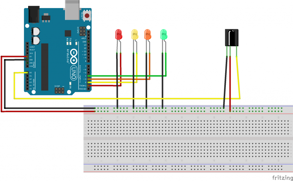
CIRCUIT DIAGRAM
CODE
#include <IRremote.h>
#define irPin A0
IRrecv irrecv(irPin);
decode_results results;
#define r1 1
int relay1 = LOW;
#define r2 2
int relay2 = LOW;
#define r3 3
int relay3 = LOW;
#define r4 4
int relay4 = LOW;
void setup()
{
  Serial.begin(19200);
irrecv.enableIRIn();
pinMode(r1, OUTPUT);
pinMode(r2, OUTPUT);
pinMode(r3, OUTPUT);
pinMode(r4, OUTPUT);
}
void loop() {
if (irrecv.decode(&results)) {
  Serial.println(results.value);
switch (results.value) {
case 33441975 :
digitalWrite(r1,LOW);
digitalWrite(r2,LOW);
digitalWrite(r3,LOW);
digitalWrite(r4,LOW); //all off
delay(100);
break;
case 33444015:
relay1 = ~ relay1;
digitalWrite(r1,relay1);//r1 on
delay(100);
break;
case 33478695:
relay2 = ~ relay2;
digitalWrite(r2,relay2);//r2 on
delay(100);
break;
case 33486855:
relay3 = ~ relay3;
digitalWrite(r3,relay3);//r3 on
delay(100);
break;
case 33435855:
relay4 = ~ relay4;
digitalWrite(r4,relay4);//r4 on
delay(100);
break;
}
irrecv.resume();
}
}


