The Gesture-Controlled Robotic Arm is an Arduino project featuring servo motors for arm recognition and movement. Three master servos dictate the motion, replicated by corresponding slave servos. An Arduino microcontroller reads master servo positions via analog inputs, mapping them to angles for slave servos connected to PWM output pins. Initialization of servos, continuous position reading of master servos, and updating of slave servos ensure synchronized movement. This setup offers precise control for applications like robotic arms and mechanical systems, ensuring harmonious joint motion akin to human arms, crucial for precise tasks. Gesture-Controlled Robotic Arm project illustrates servo control principles using microcontrollers for managing multiple motors in real-time, laying the groundwork for advanced robotic systems. Serial debugging aids in monitoring and optimizing slave servo performance to achieve synchronized operation with master servos.
Components used in this project are:
- Arduino UNO with cable
- Servo Motor (TowerPro996R) x 6
- Small Breadboard
- Male to Male Jumper Wires x 28
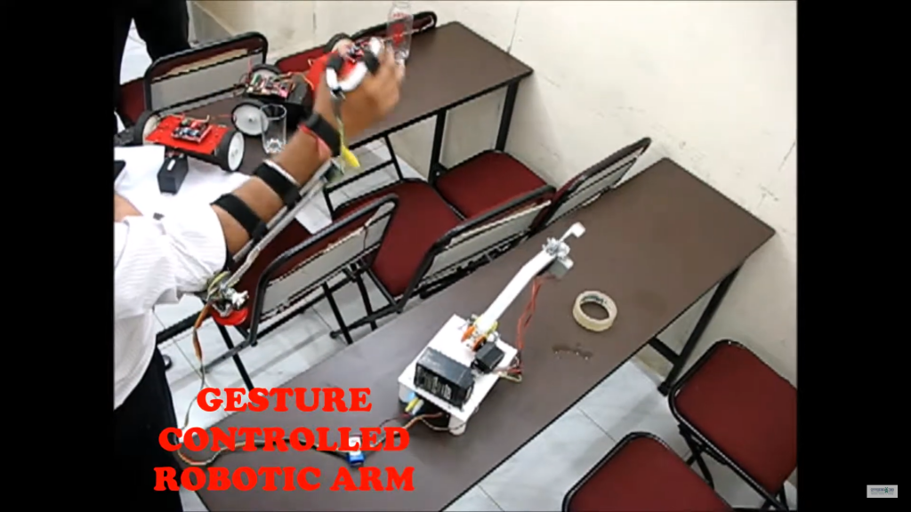
Featured Image:
Pin Connection:
Servo Motor:
- Servo Motor 1: 5V to red wire, GND to black wire, Signal -> Arduino Analog Pin 0
- Servo Motor 2: 5V to red wire, GND to black wire, Signal -> Arduino Analog Pin 1
- Servo Motor 3: 5V to red wire, GND to black wire, Signal -> Arduino Analog Pin 2
- Servo Motor 4: 5V to red wire, GND to black wire, Signal -> Arduino Digital Pin 9
- Servo Motor 5: 5V to red wire, GND to black wire, Signal -> Arduino Digital Pin 10
- Servo Motor 6: 5V to red wire, GND to black wire, Signal -> Arduino Digital Pin 11
Circuit Diagram:
Code:
#include <Servo.h>

Servo masterServos[3];
Servo slaveServos[3];

const int masterPins[3] = {A0, A1, A2}; // Analog pins to read master servo positions
const int slavePins[3] = {9, 10, 11};   // PWM pins to control slave servos

void setup() {
  for (int i = 0; i < 3; i++) {
    masterServos[i].attach(masterPins[i]);
    slaveServos[i].attach(slavePins[i]);
  }
  Serial.begin(9600);
}

void loop() {
  for (int i = 0; i < 3; i++) {
    // Read the master servo position
    int masterPos = analogRead(masterPins[i]);

    // Map the analog reading (0-1023) to servo angle (0-180)
    int angle = map(masterPos, 0, 1023, 0, 180);

    // Write the angle to the corresponding slave servo
    slaveServos[i].write(angle);

    // Print the angle for debugging
    Serial.print("Master ");
    Serial.print(i);
    Serial.print(" Position: ");
    Serial.print(masterPos);
    Serial.print(" - Slave ");
    Serial.print(i);
    Serial.print(" Angle: ");
    Serial.println(angle);
  }

  // Small delay for stability
  delay(15);
}


