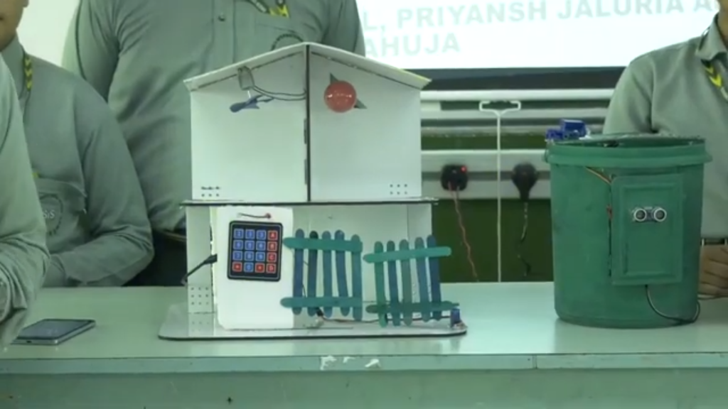
Smart home is an Arduino project with wireless control and security features. Smart home system uses two Arduino boards, Bluetooth modules, relays, a keypad, and a servo motor for an automatic door lock. The first Arduino is the main control unit for home appliances. It is connected to a Bluetooth module and relays. The Bluetooth module allows the Arduino to receive commands wirelessly from a smartphone or another Bluetooth-enabled device. The relays act as switches to turn on and off appliances like lights, fans, or other electrical devices based on the received commands. The second Arduino handles the automatic door lock system. It is equipped with a keypad and a servo motor. The keypad is used to enter a password to unlock the door. When the correct password is entered, the Arduino sends a signal to the servo motor. The servo motor then rotates to unlock the door. If the password is incorrect, the door remains locked. This smart home system allows users to control their home appliances remotely using Bluetooth and ensures security with an automatic door lock controlled by a keypad and servo motor. This setup can make daily life more convenient and secure.
Components Used:
- Arduino Uno x 2
- Bluetooth Module HC-05
- Relay single channel x 2
- Keypad
- Servo Motor
- DC Motor 5V
- Bulb with Holder
- Resistor [220 ohm]X2
- LED X2
- Male to Male Jumper Wire, X 8
- Male to Female Jumper Wire X4
Pin Connection:
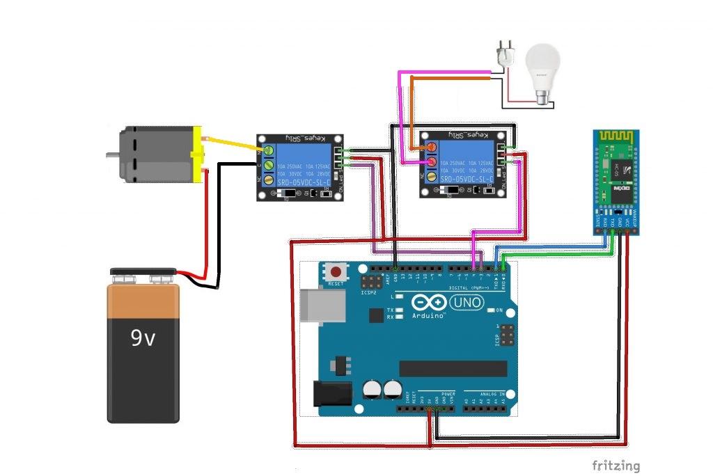
For First Arduino:
- Bluetooth Module:
- VCC to 5V
- GND to GND
- TX to RX (Digital Pin 0)
- RX to TX (Digital Pin 1)
- Relay Module:
- VCC to 5V
- GND to GND
- IN1 to Digital Pin 3 (for Appliance 1)
- IN2 to Digital Pin 4 (for Appliance 2)
- Connect appliances to relay output terminals along with external power supply.
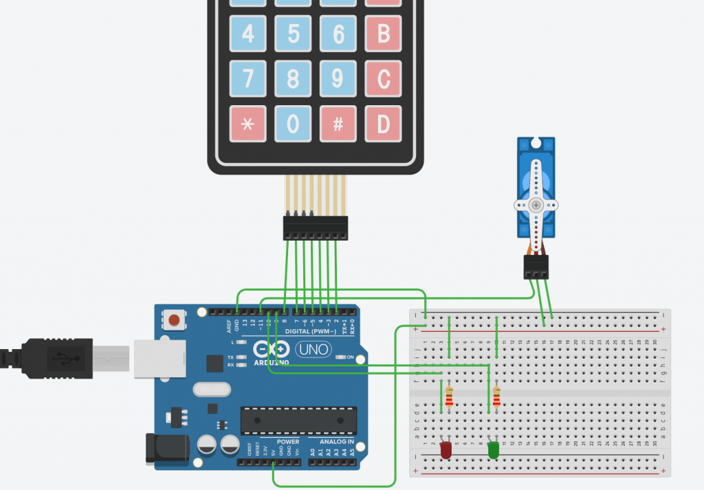
For Second Arduino:
- Keypad:
- Connect row pins (R1-R4) to Digital Pins 9-6
- Connect column pins (C1-C3) to Digital Pins 5-2
- Servo Motor:
- Signal pin to Digital Pin 11
- VCC to 5V
- GND to GND
- LED RED:
- Anode (long leg) to Digital Pin 10 through a 220-ohm resistor
- Cathode to GND
- Green LED:
- Anode (long leg) to Digital Pin 9 through a 220-ohm resistor
- Cathode to GND
CODE for First Arduino UNO:
String val;

#define relay1 3
#define relay2 4

void setup() {

  pinMode(relay1, OUTPUT);
  pinMode(relay2, OUTPUT);
  Serial.begin(9600);
  digitalWrite(relay1, LOW);
  digitalWrite(relay2, LOW);
}

void loop() {

  if (Serial.available())
  {
    val = Serial.read();
    Serial.println(val);

    if (val == 'Light ON') {
      digitalWrite(relay2, HIGH);
    }
    if (val == 'Light OFF') {
      digitalWrite(relay2, LOW);
    }
    if (val == 'Fan ON') {
      digitalWrite(relay2, HIGH);
    }
    if (val == 'Fan OFF') {
      digitalWrite(relay2, LOW);
    }
    delay(100);
  }
}
CODE for Second Arduino UNO:
//Install "Keypad" library from library manager

#include <Servo.h>
#include <Keypad.h>

const int servoPin = 11; // Servo motor control pin
const int RLed = 10;    //Red LED pin
const int GLed = 11;    //Green LED pin
Servo myServo;

const int ROW_NUM = 4; // four rows
const int COLUMN_NUM = 4; // four columns
char keys[ROW_NUM][COLUMN_NUM] = {
  {'1','2','3','A'},
  {'4','5','6','B'},
  {'7','8','9','C'},
  {'*','0','#','D'}
};
byte pin_rows[ROW_NUM] = {9, 8, 7, 6}; // connect to the row pinouts of the keypad
byte pin_column[COLUMN_NUM] = {5, 4, 3, 2}; // connect to the column pinouts of the keypad

Keypad keypad = Keypad(makeKeymap(keys), pin_rows, pin_column, ROW_NUM, COLUMN_NUM);

String correctPassword = "1234";
String enteredPassword = "";

void setup() {
  Serial.begin(9600);
  myServo.attach(servoPin);
  myServo.write(90); // Set servo to the initial position
  pinMode(RLed, OUTPUT);
pinMode(GLed, OUTPUT);
}

void loop() {
  char key = keypad.getKey();

  if (key) {
    if (key == '#') {
      // Check if the entered password is correct
      if (enteredPassword == correctPassword) {
        Serial.println("Password Correct! Access Granted.");
        digitalWrite(GLed, HIGH);
        digitalWrite(RLed, LOW);
        rotateServo();
      } else {
        Serial.println("Incorrect Password! Access Denied.");
        digitalWrite(RLed, HIGH);
        digitalWrite(GLed, LOW);
      }

      // Reset entered password
      enteredPassword = "";
    } else {
      // Append the pressed key to the entered password
      enteredPassword += key;
      Serial.print("Entered Password: ");
      Serial.println(enteredPassword);
    }
  }
}

void rotateServo() {
  // Rotate the servo to 180 degrees (unlock position)
  myServo.write(180);
  delay(2000); // Wait for 2 seconds
  // Rotate the servo back to 90 degrees (lock position)
  myServo.write(90);
}


