DG Medication Project introduces an advanced health monitoring system that combines NodeMCU, Arduino, a pulse rate sensor, an I2C LCD, and the Blynk app. This smart system is designed to accurately collect health data and enable timely interventions, especially beneficial for patients living near hospitals. Students can explore how technology like NodeMCU and Arduino can revolutionize healthcare by providing real-time health data monitoring and alerts through a user-friendly mobile app like Blynk. This project promotes patient care and demonstrates IoT’s potential to improve healthcare accessibility and outcomes.
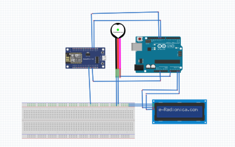
Components/Circuit:
- NodeMCU (ESP8266): Manages data transmission and communication with the Blynk app.
- Arduino Nano: Controls sensor readings and LCD operations.
- Pulse Rate Sensor: Monitors heart rate for health assessment.
- I2C LCD Display: Shows real-time health data and alerts.
- Blynk App: Enables remote health monitoring and alerts on mobile devices.
CODE FOR ARDUINO
Here is the Arduino code that handles the Pulse Sensor and the I2C LCD, and communicates with the ESP8266:


#include <Wire.h>
#include <LiquidCrystal_I2C.h>
#include <SoftwareSerial.h>

#define USE_ARDUINO_INTERRUPTS true
#include <PulseSensorPlayground.h>  // Include PulseSensor Library

// Pulse Sensor variables
const int PulseSensorPin = A0;       // Pulse Sensor signal connected to A0
PulseSensorPlayground pulseSensor;   // Create an instance of the PulseSensorPlayground object

// Define software serial pins for ESP8266
#define ESP_RX_PIN 10 // Arduino Pin 10 -> ESP8266 TX
#define ESP_TX_PIN 11 // Arduino Pin 11 -> ESP8266 RX

SoftwareSerial espSerial(ESP_RX_PIN, ESP_TX_PIN);

// Set the LCD address to 0x27 for a 16 chars and 2 line display
LiquidCrystal_I2C lcd(0x27, 16, 2);

void setup() {
  // Initialize Serial and Software Serial
  Serial.begin(9600);
  espSerial.begin(9600);

  // Initialize the LCD
  lcd.begin();
  lcd.backlight();
  lcd.clear();
  lcd.print("Heart Rate:");

  // Initialize Pulse Sensor
  pulseSensor.analogInput(PulseSensorPin);
  pulseSensor.setThreshold(550);  // Adjust this threshold value to fit your needs
  pulseSensor.begin();

  // Set up interrupt
  attachInterrupt(digitalPinToInterrupt(PulseSensorPin), onPulseSensorData, FALLING);
}

void loop() {
  // Process commands from ESP8266 (if any)
  if (espSerial.available() > 0) {
    String cmd = espSerial.readStringUntil('\n');
    if (cmd.startsWith("BPM:")) {
      int bpm = cmd.substring(4).toInt();
      // Handle the BPM value received from ESP8266 (if needed)
    }
  }
}

void onPulseSensorData() {
  if (pulseSensor.sawNewSample()) {
    int bpm = pulseSensor.getBeatsPerMinute();
    Serial.println("♥  A HeartBeat Happened !");
    Serial.println(String("BPM: ") + bpm);

    // Update the LCD with the BPM value
    lcd.setCursor(0, 1);
    lcd.print("BPM: ");
    lcd.print(bpm);
    lcd.print("   "); // Clear remaining characters

    // Send the BPM value to ESP8266
    espSerial.print("BPM:");
    espSerial.println(bpm);
  }
}
CODE FOR ESP8266
Here’s the ESP8266 code that handles the Wi-Fi and Blynk connection:


#include <ESP8266WiFi.h>
#include <BlynkSimpleEsp8266.h>
#include <SoftwareSerial.h>

// Fill-in information from your Blynk Template here
#define BLYNK_TEMPLATE_ID "___"
#define BLYNK_DEVICE_NAME "____"
#define BLYNK_AUTH_TOKEN "_____"

char auth[] = BLYNK_AUTH_TOKEN;
char ssid[] = "*****";
char pass[] = "*****";

BlynkTimer timer;
SoftwareSerial arduinoSerial(D2, D3); // RX, TX

void setup() {
  // Initialize Blynk
  Blynk.begin(auth, ssid, pass);
  arduinoSerial.begin(9600);

  // Set up a timer to call the sensor function every second
  timer.setInterval(1000L, sensor);
}

void loop() {
  Blynk.run();
  timer.run();
}

void sensor() {
  // Read BPM value from Arduino
  if (arduinoSerial.available() > 0) {
    String bpmString = arduinoSerial.readStringUntil('\n');
    if (bpmString.startsWith("BPM:")) {
      int bpm = bpmString.substring(4).toInt();
      Serial.println(String("Received BPM: ") + bpm);
      Blynk.virtualWrite(V0, bpm);
    }
  }
}
How it Works:
- Heart Rate Monitoring: The pulse rate sensor tracks heart rate data in real-time.
- Data Processing: Arduino processes sensor data and communicates with NodeMCU.
- Data Transmission: NodeMCU sends health data to the Blynk app for remote monitoring.
- Alert System: The Blynk app notifies users of critical health events or abnormalities.
Setup:
- Hardware: Connect NodeMCU, Arduino Nano, pulse rate sensor, and I2C LCD, and configure with the Blynk app.
- Programming: Develop code for Arduino and NodeMCU to read sensor data, display on LCD, and transmit data to the Blynk app.
Advantages:
- Real-time Monitoring: Provides instant health data updates for proactive interventions.
- Remote Monitoring: Allows caregivers to monitor patient health remotely via the Blynk app.
- Health Alerts: Notifies users of critical health events for timely medical attention.
- User-Friendly Interface: The Blynk app offers an intuitive platform for health data visualization and management.


