An obstacle-avoiding robot is an autonomous robotic system designed to navigate through its environment while detecting and avoiding obstacles in its path. This robot utilizes an ultrasonic sensor for obstacle detection, an Arduino Uno microcontroller for processing, and a motor driver to control the movement of the motors. This project demonstrates the integration of hardware components and programming to achieve autonomous navigation.
Key Components:
- Arduino Uno:
- Acts as the brain of the robot, processing sensor data and controlling the motors based on this data.
- Reads inputs from the ultrasonic sensor and sends output signals to the motor driver.
- Ultrasonic Sensor (HC-SR04):
- Measures the distance to obstacles in front of the robot.
- Consists of a transmitter and receiver; the transmitter emits ultrasonic waves and the receiver detects the reflected waves.
- Provides distance data to the Arduino for obstacle detection.
- Motor Driver (L298N):
- Controls the speed and direction of the DC motors.
- Receives control signals from the Arduino to drive the motors forward, backward, or to stop.
- DC Motors and Wheels:
- Provide mobility to the robot.
- Controlled by the motor driver to move the robot in different directions.
- Chassis:
- The structure that holds all the components together, including the Arduino, sensor, motors, and power supply.
Working Principle:
- Initialization:
- When powered on, the Arduino initializes all connected components, including setting up the pins for the ultrasonic sensor and motor driver.
- Obstacle Detection:
- The ultrasonic sensor continuously emits ultrasonic waves. When these waves hit an obstacle, they bounce back to the sensor.
- The Arduino calculates the distance to the obstacle based on the time it takes for the waves to return.
- Decision Making:
- If the measured distance is less than a predefined threshold (indicating an obstacle is close), the Arduino decides to stop or change direction.
- If no obstacle is detected within the threshold, the robot continues to move forward.
- Motor Control:
- Based on the decision made by the Arduino, control signals are sent to the motor driver.
- The motor driver adjusts the speed and direction of the motors accordingly.
Code is given below:
#include  <NewPing.h>        //Ultrasonic sensor function library. You must install this library
#include  <Servo.h>          //Servo motor library. This is standard library


const  int LeftMotorForward = 2;
const int LeftMotorBackward = 3;
const int RightMotorForward  = 4;
const int RightMotorBackward = 5;

//sensor pins
#define trig_pin  A1 //analog input 1
#define echo_pin A2 //analog input 2

#define maximum_distance  200
boolean goesForward = false;
int distance = 100;

NewPing sonar(trig_pin,  echo_pin, maximum_distance); //sensor function
Servo servo_motor; //our servo  name


void setup(){

  pinMode(RightMotorForward, OUTPUT);
  pinMode(LeftMotorForward,  OUTPUT);
  pinMode(LeftMotorBackward, OUTPUT);
  pinMode(RightMotorBackward,  OUTPUT);

  servo_motor.attach(8); //our servo pin

  servo_motor.write(115);
  delay(2000);
  distance = readPing();
  delay(100);
  distance = readPing();
  delay(100);
  distance = readPing();
  delay(100);
  distance = readPing();
  delay(100);
}

void loop(){

  int distanceRight = 0;
  int  distanceLeft = 0;
  delay(50);

  if (distance <= 20){
    moveStop();
    delay(300);
    moveBackward();
    delay(400);
    moveStop();
    delay(300);
    distanceRight = lookRight();
    delay(300);
    distanceLeft  = lookLeft();
    delay(300);

    if (distance >= distanceLeft){
      turnRight();
      moveStop();
    }
    else{
      turnLeft();
      moveStop();
    }
  }
  else{
    moveForward();
  }
    distance = readPing();
}

int  lookRight(){
  servo_motor.write(50);
  delay(500);
  int distance =  readPing();
  delay(100);
  servo_motor.write(115);
  return distance;
}

int  lookLeft(){
  servo_motor.write(170);
  delay(500);
  int distance = readPing();
  delay(100);
  servo_motor.write(115);
  return distance;
  delay(100);
}

int  readPing(){
  delay(70);
  int cm = sonar.ping_cm();
  if (cm==0){
    cm=250;
  }
  return cm;
}

void moveStop(){

  digitalWrite(RightMotorForward,  LOW);
  digitalWrite(LeftMotorForward, LOW);
  digitalWrite(RightMotorBackward,  LOW);
  digitalWrite(LeftMotorBackward, LOW);
}

void moveForward(){

  if(!goesForward){

    goesForward=true;

    digitalWrite(LeftMotorForward,  HIGH);
    digitalWrite(RightMotorForward, HIGH);

    digitalWrite(LeftMotorBackward,  LOW);
    digitalWrite(RightMotorBackward, LOW);
  }
}

void moveBackward(){

  goesForward=false;

  digitalWrite(LeftMotorBackward, HIGH);
  digitalWrite(RightMotorBackward,  HIGH);

  digitalWrite(LeftMotorForward, LOW);
  digitalWrite(RightMotorForward,  LOW);

}

void turnRight(){

  digitalWrite(LeftMotorForward,  HIGH);
  digitalWrite(RightMotorBackward, HIGH);

  digitalWrite(LeftMotorBackward,  LOW);
  digitalWrite(RightMotorForward, LOW);

  delay(500);

  digitalWrite(LeftMotorForward, HIGH);
  digitalWrite(RightMotorForward, HIGH);

  digitalWrite(LeftMotorBackward, LOW);
  digitalWrite(RightMotorBackward,  LOW);


}

void turnLeft(){

  digitalWrite(LeftMotorBackward,  HIGH);
  digitalWrite(RightMotorForward, HIGH);

  digitalWrite(LeftMotorForward,  LOW);
  digitalWrite(RightMotorBackward, LOW);

  delay(500);

  digitalWrite(LeftMotorForward, HIGH);
  digitalWrite(RightMotorForward, HIGH);

  digitalWrite(LeftMotorBackward, LOW);
  digitalWrite(RightMotorBackward,  LOW);
}
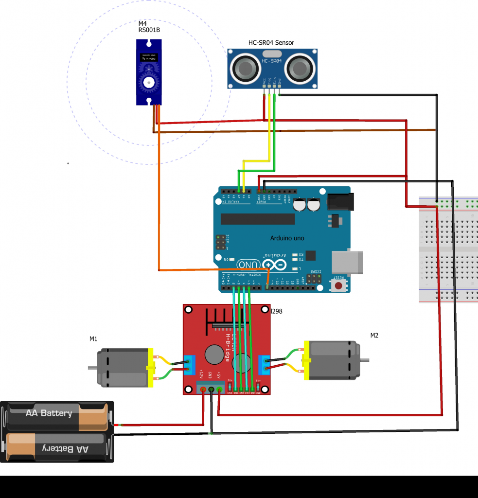
The circuit diagram is given below: