In this video, we have made 2 projects:
1. Color Blindness Machine Project
2. Medicine Reminder project
Let’s begin with our first project:
COLOR BLINDNESS MACHINE
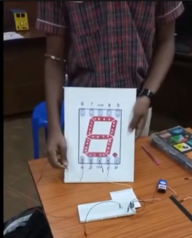
Color blindness is a common condition where people have trouble telling certain colors apart, which can affect their daily activities and work. This project aims to create a simple tool to detect color blindness using an Arduino Nano. The system has two panels: one for the person testing and one for the person being tested. By checking how the person responds to different colors, the system can tell if they are color blind.
The project uses an Arduino Nano, 7 LEDs, and 12 switches to make this tool. The system has a control panel and a result panel.

Components Required
- Arduino Nano: The microcontroller used to control the system.
- LEDs (7 units): Used to display colors corresponding to the control panel switches.
- Different colors for each LED (e.g., Red, Green, Blue, Yellow, etc.)
- Switches (12 units): Used as inputs on the control and result panels.
- 6 switches labeled with numbers (1 to 6) for the control panel.
- 6 switches labeled with color names for the result panel.
- Resistors (12 units): Used for switches to prevent short circuits and control current.
- Breadboard and Jumper Wires: For setting up the circuit connections.
- Power Supply: To power the Arduino Nano and LEDs.
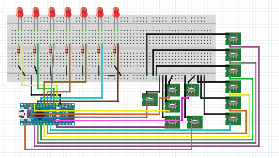
Circuit Connection
- LED Connections:
- Connect each of the 7 LEDs to the Arduino Nano pins D2 to D8.
- Connect the cathode (negative) of each LED to the ground through a resistor (220Ω to 330Ω).
- Control Panel Switches:
- Connect one terminal of each switch to the Arduino Nano pins D9 to A1.
- Connect the other terminal of each switch to the ground.
- Result Panel Switches:
- Connect one terminal of each switch to the Arduino Nano pins A2 to A7.
- Connect the other terminal of each switch to the ground.
Circuit Diagram is given below:
Working
- Setup:
- Initialize the Arduino Nano, setting the LED pins as OUTPUT and the switch pins as INPUT.
- Operation:
- The tester (doctor) presses a switch on the control panel, which turns on the corresponding LED that displays a specific color.
- The person being tested observes the lit LED and presses the switch on the result panel that they believe matches the color of the LED.
- The system compares the switch pressed on the control panel with the switch pressed on the result panel.
- Detection:
- If the switch on the result panel matches the switch on the control panel, the 7th LED (indicator) lights up, indicating the person is not color blind.
- If the switches do not match, the 7th LED remains off, indicating potential color blindness.

The code is given below:
// Define LED pins
const int ledPins[7] = {2, 3, 4, 5, 6, 7, 8};

// Define switch pins for control panel
const int controlPanelPins[6] = {9, 10, 11, 13, A0, A1};

// Define switch pins for result panel
const int resultPanelPins[6] = {A2, A3, A4, A5, A6, A7};

// Variable to store switch states
bool controlPanelStates[6];
bool resultPanelStates[6];

void setup() {
  // Initialize LED pins as OUTPUT
  for (int i = 0; i < 7; i++) {
    pinMode(ledPins[i], OUTPUT);
  }

  // Initialize control panel switch pins as INPUT
  for (int i = 0; i < 6; i++) {
    pinMode(controlPanelPins[i], INPUT);
    pinMode(resultPanelPins[i], INPUT);
  }
}

void loop() {
  // Read control panel switch states
  for (int i = 0; i < 6; i++) {
    controlPanelStates[i] = digitalRead(controlPanelPins[i]);
  }

  // Read result panel switch states
  for (int i = 0; i < 6; i++) {
    resultPanelStates[i] = digitalRead(resultPanelPins[i]);
  }

  // Control LEDs based on control panel switches
  for (int i = 0; i < 6; i++) {
    digitalWrite(ledPins[i], controlPanelStates[i]);
  }

  // Control the 7th LED based on both panels
  bool anyMatch = false;
  for (int i = 0; i < 6; i++) {
    if (controlPanelStates[i] && resultPanelStates[i]) {
      anyMatch = true;
      break;
    }
  }
  digitalWrite(ledPins[6], anyMatch);
}
Let’s begin our second project:
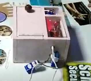
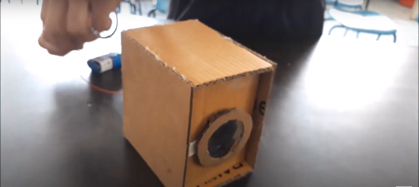
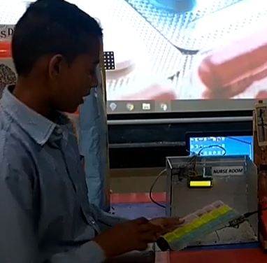
MEDICINE REMINDER
In this project, we’ll make an innovation using an Arduino that helps detect medicine. When the medicine is detected, it will turn on a buzzer and a blue LED. We’ll also have a green LED to show that the device is powered on and working properly. Let’s look at what we need and how it works!
Components Required:
- Arduino: This is like the brain of our project. It controls everything.
- Buzzer: This makes a sound when the medicine is detected.
- Blue LED: This light turns on when the medicine is detected.
- Green LED: This light stays on to show the device is working.
- IR Sensor: This sensor detects the presence of the medicine.
- Resistor: 220 ohm resistor to protect the LED.
- Jumper wires: Male-to-male and male-to-female jumper Wires for connection.
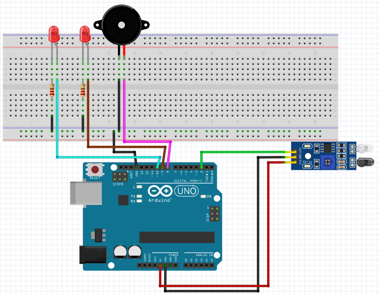
Circuit Connections:
IR Sensor:
- VCC: Connect to 5V on the Arduino
- GND: Connect to GND on the Arduino
- OUT: Connect to digital pin 2 on the Arduino
Buzzer:
- Positive lead: Connect to digital pin 8 on the Arduino
- Negative lead: Connect to GND on the Arduino
LEDs:
- Blue LED:
- Anode (+): Connect to digital pin 9 on the Arduino through a 220-ohm resistor
- Cathode (-): Connect to GND on the Arduino
- Green LED:
- Anode (+): Connect to digital pin 10 on the Arduino through a 220-ohm resistor
- Cathode (-): Connect to GND on the Arduino
Circuit Diagram is given below:
Working:
- Power On: When we connect our device to power, the green LED will turn on. This tells us that the device is ready to work.
- Medicine Detection: The IR sensor is always looking for medicine. If it sees the medicine, it sends a signal to the Arduino.
- Alert: When the Arduino gets the signal from the IR sensor, it turns on the blue LED and the buzzer. This lets us know that medicine has been detected.
Code is given below:
// Define pin connections
const int irSensorPin = 2; // Pin connected to the IR sensor
const int buzzerPin = 8;   // Pin connected to the buzzer
const int ledBluePin = 9;  // Pin connected to the blue LED
const int ledGreenPin = 10; // Pin connected to the green LED

void setup() {
  // Initialize serial communication for debugging
  Serial.begin(9600);

  // Set pin modes
  pinMode(irSensorPin, INPUT);
  pinMode(buzzerPin, OUTPUT);
  pinMode(ledBluePin, OUTPUT);
  pinMode(ledGreenPin, OUTPUT);

  // Ensure the buzzer and LEDs are off initially
  digitalWrite(buzzerPin, LOW);
  digitalWrite(ledBluePin, LOW);
  digitalWrite(ledGreenPin, LOW);
}

void loop() {
  // Read the IR sensor value
  int sensorValue = digitalRead(irSensorPin);

  // Debugging: print the sensor value
  Serial.println(sensorValue);

  // If the sensor detects the medicine (sensor value high), turn the buzzer and blue LED on
  if (sensorValue == HIGH) {
    digitalWrite(buzzerPin, HIGH);
    digitalWrite(ledBluePin, HIGH);
    digitalWrite(ledGreenPin, LOW);
    Serial.println("Medicine detected - Buzzer ON, Blue LED ON, Green LED OFF");
  }
  // If the sensor does not detect the medicine (sensor value low), turn the buzzer and blue LED off, green LED on
  else {
    digitalWrite(buzzerPin, LOW);
    digitalWrite(ledBluePin, LOW);
    digitalWrite(ledGreenPin, HIGH);
    Serial.println("No medicine - Buzzer OFF, Blue LED OFF, Green LED ON");
  }

  // Add a small delay to avoid bouncing
  delay(100);
}